Laser Cutting Airfoils – Calibration
- July 12th, 2011
- Write comment
Power Setting Calibration
Having generated airfoil templates previously, the next step towards creating hot-wire templates was to get them cut. Thanks to a generous sponsorship, this was accomplished by using Techshop RDU’s Epilog Helix 24. For these test pieces 3/8″ Birch Plywood was used.
After a few test cuts the settings that would allow the piece to be cut after a single pass. were determined to be:
Vector: Speed 15%, Power 90%, Frequency 2000 hz
Additionally, each sample piece was labeled with the source file and dimensions by including a rasterized text. The settings used were:
Raster: Speed 25 % Power 80%
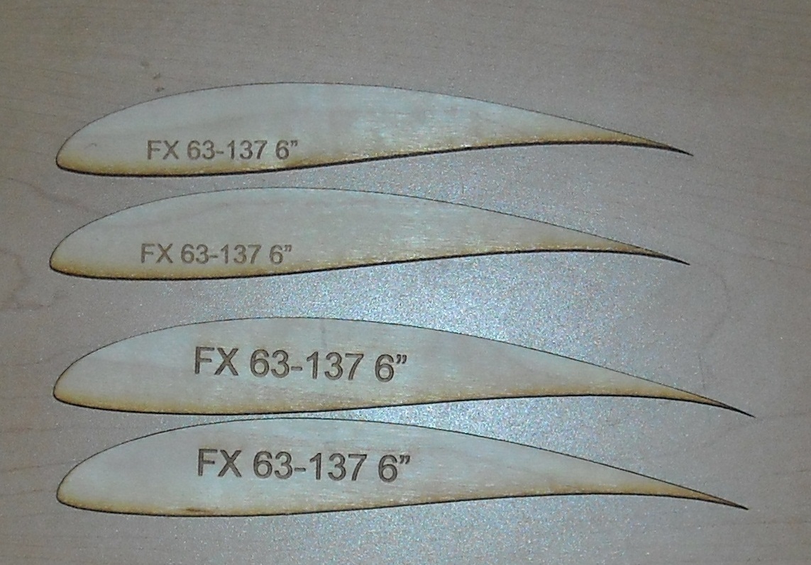
While the airfoils were an interesting piece to cut, the reader may clearly observe that in the above image the two six inch chord length airfoils are not the same size. In fact, neither airfoil came out at six inches. The smaller airfoil measured 5.8″ and the larger one measured 6.2″.
The cause of this is that while the laser’s cut is very fine, it does still have a thickness. On the thin trailing edge of the airfoil this thickness results in a large effective change to the geometry. To compensate for this, the cut line needs to be offset from the desired outline by a certain amount. Determining this amount is the purpose of the calibration procedure below.
Offset Calibration
Once the settings that will be used for cutting the airfoil have been determined, the offset required may be calculated. To do this start by cutting a rectangle. The dimensions are arbitrary, so the actual size doesn’t matter. During these tests, the setting used to cut the rectangle were etched into the side so they wouldn’t be lost. After cutting, measure the width of the rectangle and the width of the rectangle’s cutout from the source material. Subtracting these two measurements and then dividing by two then gives you the the offset to be used for that material.
The calibration can be applied to the laser template in Corel Draw during the below setup procedure.
- Open airfoil *.svg
- Move airfoil to desired (x,y) position, usually upper left corner
- Right-click and unlock airfoil pattern
- Click on line and then select all (ctrl-a)
- Select “Contour” option from menu
- Set contour size according to the calibration results
- Right-click and select “Break group apart”
- Select all the points on the new contour and set the line width to “hairline”, click apply afterwards
- Delete original airfoil
- Add label text, right-click and select “convert to curves”
- Print to Epilog Laser Cutter using correct settings under properties
