3D Printed Plug
- April 12th, 2012
- Write comment
In the process of manufacturing a senior design aircraft, a plug is used to create a negative mold on which aircraft fuselage skins can be laid up. When the 2010-2011 senior design groups fabricated fuselage plugs, it was a lengthy process involving foam, plywood, fiberglass, epoxy, bondo, spackle, and an incredible amount of sanding.
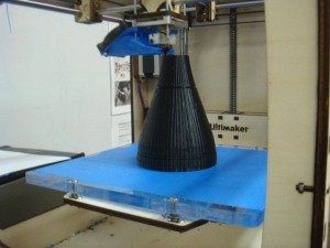
This year a new method was tried with the intent of reducing the time required to manufacture the plug and allow for more complex geometric shapes to be used. The availability of cheap rapid prototyping machines made this possible. For this experiment the Ultimaker 3D printer in the Entrepreneurship Garage was used. Based on previous experiments, PLA was used as the printed material. North Carolina State University’s Aerospace Engineering Senior Design teams 3 and 4 participated in the experiment and provided the labor to integrate the printed parts into their aircraft plugs.
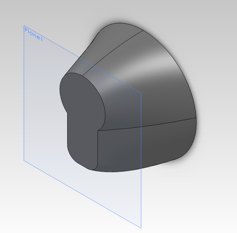
During the fall semester, the seniors designed the fuselage in solidworks. The designs used a section of off-the-shelf PVC tubing as the main body with a nose cone and tail cone on either end to create the plug. The nose and tail cones were modeled as separate parts and exported to *.STL format.
The UltireplicatorG software was then used to “slice” the model and create a GCODE instructions that the 3D printer could use. In total, four parts were to be printed for the two teams. Over the course of the printing a number of settings were experimented with. The best results came when the solidworks models were simple solid objects with no shelling. The slicer was then configured to print the object with zero infill and walls 3 layers thick. This gave an object that was fast to print, but still rigid enough to be usable. The final thickness of the wall was roughly 2-3 millimeters.
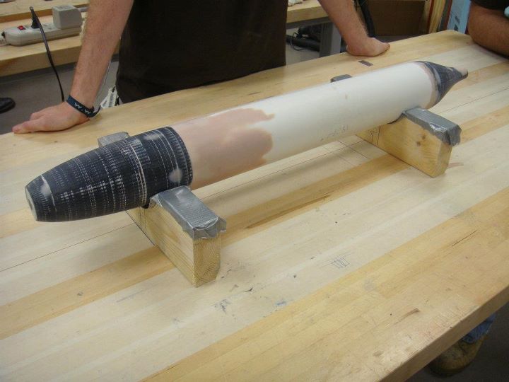
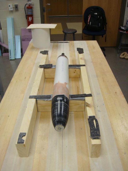
Once the printing was complete the seniors took over the process. First an internal frame was cut to support, center, and join the cone to the PVC pipe. The cone was then filled with plaster of paris to support the surface. Bondo and spackle were then applied to the surface to fill any cracks. Team 4 also added a shaft that stuck out the end of the mold. This was then attached to a jury-rigged lathe. The shaft was removed and sanded smooth once its purpose was served.
After hours of hard work the final plugs were completed. The final sanded surface is so smooth that reflections are clearly seen on its surface.
With the plugs complete the teams used wax and PVA to prepare the plug for the mold layup. While team 4 did not have any trouble getting the plug out of the completed mold, team 3 did have some difficulties. However, these difficulties have been attributed to the waxing and PVA processes and not the 3D printed PLA material.
Overall the experiment was successful in its goals of reducing time to create the plug and allowing for the creating of complex geometries. In particular, sanding was reduced since only the final surface was sanded. In the old process, sanding had to be done on the foam surface, fiberglass surface, and the painted surface all of which took time. Additionally, the geometries would have been difficult to create by other methods. While team 4’s radially symmetric cones could have been created on a lathe, team3’s cones could not. The success of this method should serve as a stepping stone for future designed using more complicated geometries.


