MAVL Progress

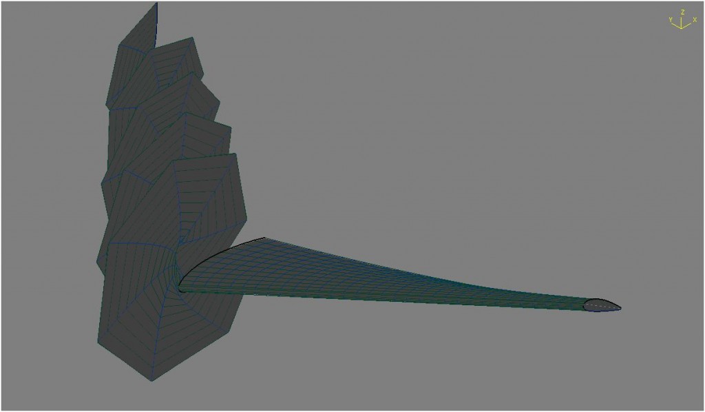
Since I last wrote I have made significant progress on MAVL.  The program is now producing results like that shown below.  Full AVL model generation is now possible; rudders, elevators, and control surfaces are all possible now.  The capabilities of MAVL have been expanded to create and run test cases as well as load data from files created by AVL.

In particular, MAVL can read files created by the ST and SB commands under the OPER menu as well as reading the *.eig file created from the MODE menu.  This allows the user to create models from design parameters and get immediate stability information all with out leaving matlab.  The parseEig function also classifies the eigenvalues based on their relative orders of magnitude.  This allows the user to quickly access the phugoid, short period, dutch roll, spiral mode, and roll convergence.

MAVL

Matlab + AVL

Athena Vortex Lattice out of MIT is a great command line tool for analyzing the stability and control of an aircraft.  In developing the S&C for my senior design project I want to use AVL and Matlab together so for the past several hours I have been working on a matlab program that creates AVL models, tests them using AVL, and then loads the results data back into matlab.  The most basic version is now working (no control surfaces yet), but along the way there were some interesting bugs…

smallBug

Senior Design and Relativity

After much anticipation this year’s senior design challenge has been unveiled.  For reference the “control system” mentioned is a piccolo II autopilot.

DesignRequirements

Each of the three teams was given a different configuration to use as mentioned by requirement 9.  My team’s configuration must either be a flying wing (one lifting surface) or have three lifting surfaces (canard, wing, elevator).

Although some parameters of the aircraft are well defined, others are a bit open ended.  For example, requirement 9 “Flight duration should be as long as possible.” begs the question how long is long enough?  This lead my to ask what endurance does my personal aircraft get.  My aircraft is a foam powered glider with a 2350 mah 3s1p battery.  Winds today were rather high, at times exceeding the cruise velocity of the aircraft.  Despite this I was able to achieve flight times of 37 minutes and 43 minutes.  Given the poor condition of my aircraft and the larger battery of our senior design aircraft I feel that we should be able to double that endurance at a minimum.

History Time : Darwin

I found this a program on my computer that I wrote as a freshman years ago.  It is a simple artificial organism with the capability to evolve in order to better survive in its environment.  In this version (1.2)  the organisms have no intelligence to use to find the food; another green blob that jumps around the map.  Only by reproducing and dying can the organisms appear to follow the food.  The motion of each individual is simply a random walk.

The actions of the organism are randomly chosen each cycle with the likelihood of each action being determined by its DNA.  Each off-spring will vary one of these parameters by a preset value.  In the readout on the right several parameters are displayed to give the observer some insight into the organism.  The averages give insight into the DNA of the organisms.  The program will occasionally get stuck with one or more immortal cells, press the red button to restart the program.

Read more

Making TI and Arduino Talk

Previously simulink was used to program Texas Intrument’s F28335 Delfino processor to simply command a servo through a sine wave.  Since then two more important milestones have been covered; IMU communication and single channel PPM reading.  In both cases the challenge is to correctly configure the existing simulink blocks.

Getting the IMU communication to work was extra challenging because both simulink and the IMU firmware needed to be set-up to communicate.  The IMU is a sparkfun 9-dof board.  This handy board reads three axises of acceleration, gyration, and magnetism.  The board’s MCU contains an atmega328 with the arduino bootloader.  Finally, there is software that can be downloaded to the board to combine the sensor data to get the roll, pitch, and yaw of the board.  By adding the below output option to the output section of the code I can make it send its values in a binary form that the Delfino can read.

if PRINT_BINARY == 1
//Start Character
Serial.print(“S”);
unsigned char lowByte, highByte;
unsigned int val;
//Roll
val = ToDeg(roll)*100;
lowByte = (unsigned char)val;
highByte = (unsigned char)(val >> 8);
Serial.print(lowByte, BYTE);
Serial.print(highByte, BYTE);
//Pitch
val = ToDeg(pitch)*100;
lowByte = (unsigned char)val;
highByte = (unsigned char)(val >> 8);
Serial.print(lowByte, BYTE);
Serial.print(highByte, BYTE);
//Yaw
val = ToDeg(yaw)*100;
lowByte = (unsigned char)val;
highByte = (unsigned char)(val >> 8);
Serial.print(lowByte,BYTE);
Serial.print(highByte,BYTE);
//Ending Character
Serial.print(“E”);

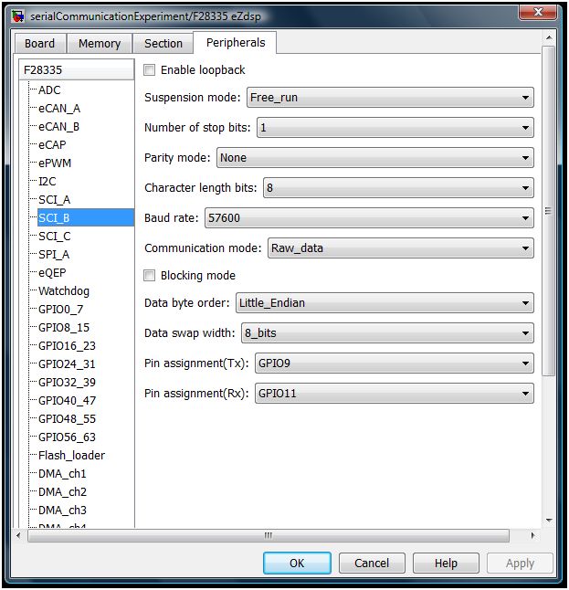
For this to work the code must be set to only output this binary message and do so at 57600 baud.  At higher speeds this board cannot keep up and will send erroneous data which will mess up simulink’s parsing.

On the simulink side, the “Target Preferences block” (In this case F28335 eZdsp) needs to be configured as shown below.

F28335a

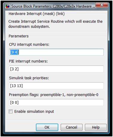
The Standard Communication Interface (SCI) module is placed inside of a function which is called by the interrupt handler.  In simulink the top level of the program will look like below.  The demux block after the interrupt block allows the IMU and PWM read to both use the interrupt block and still be called at the correct time.  This is done because each simulink model may only contain a single “Hardware Interrupt” block.headThe Interrupt is then configured to look like the below:

interruptThe first number in each field is related to the SCI interrupt while the second number in each field is for the PPM reader.

The inside of the function includes the SCI module as well as an example use of the data and a GPIO to warn of errors.imuTI

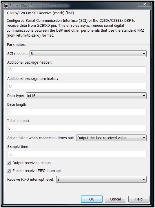
The SCI module should be configured as shown below.

F28335b

Simulink Hardware Servo Block

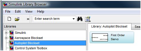
Simulink libraries perform complex functions and augment the capabilities of the Simulink software.  With libraries like the Aerospace Blockset, complex tasks (like creating a 6 dof simulator)  are greatly simplified.  As an exercise I started what I am calling the Autopilot Blockset.  The purpose of this library is to hold the blocks that connect the control system blocks to the hardware blocks.  Although right now the library might better be called the hardware servo library, the plan is to expand the library with blocks for telemetry packets and AHRS communication.

Autopilot_Library

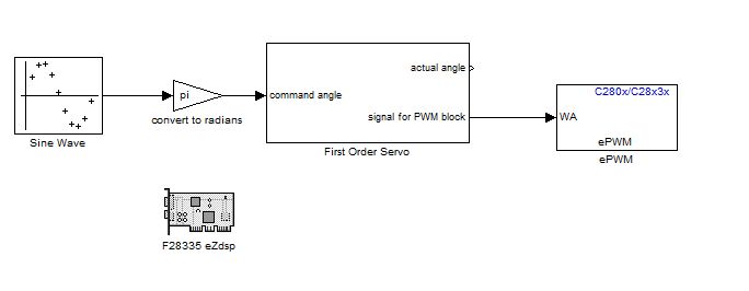
Currently the library contains just the Servo block.  This block converts the angles used by a control system into a signal the hardware can use to command the physical servo.  In testing the block was used to smoothly command a servo through a 180 degree sweep using the below model.

ServoSweep

The servo block is configured through a menu that is shown by double-clicking on the servo block.  The angle commanded by the user will be the angle of the surface it is connected to if the pulse length limits and their angles are properly configured.  In a simple example the servo arm can be setup as the controlled surface by setting the limit angles to 90 and -90.  Regardless of the commanded angle the servo will not be commanded beyond the pulse length limits.  Because of this, an actual angle output is made available which provides the actual commanded position taking into account any truncation due to limits.

Writing Piccolo Command Center Plugins – Setting up the environment

Writing plugins for the Piccolo Command Center opens up many possibilities for integrated tools.  Often these tools may need to work with other tools like the PCC’s main map.  By taking advantage of the work done by Cloud Cap Tech you can skip to developing the tool you need instead of spending time writing your own map tool from scratch.  For those interested in writing plugins the first step is to set-up the environment to write and build the plug-ins.

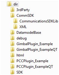
commsDirectory

Each distribution of the Piccolo software comes with a copy of the commSDK and the CloudCapPluginSDK.  These two zip files can be found under <Start><Cloud Cap Piccolo 2.x.x><Tools><Software Development>.  Unzip the CloudCapPluginSDK.zip into your working directory.  Unzip the contents of the commSDK and put them in a folder called “CommSDK”.  Put this folder in working directory.  The final directory structure should look similar to that shown to the right.

The PccPluginExamples is a Visual Studio 2005 file which will contain some examples to get you started.  Now you will want to install Visual Studio 2005 if you have not already done so.  It may be possible to compile plugins in a later version of Visual Studio, but I am not aware of any success stories for that path.  Once you have installed VS 2005 you should be able to open the PccPluginExamples file.  From the “Solution Explorer” click on “PCCPlugin_Example”. Then on the main menu selected <Build><Build PCCPlugin_Example>.  The Plug-in should compile successfully.

If the compiler complains of missing files, or you need to put the commSDK elsewhere you will need to review what paths the compiler is looking under.  These can be found by right-clicking on the line “PCCPlugin_Example” under the “Solution Explorer” and selecting properties.  The include directories can be be found under <Configuration Properties><C/C++><General>.  A similiar list for the linker can be found under <Configuration Properties><Linker>.  The libraries to be included by the linker are listed in under <Configuration Properties><Linker><Input>.  You will probably not need this information if you are using version 2.1.1.c or later.  If you are using an earlier version you may also need some of the information discussed in this thread on the cloud cap forum.

Setting up Qt with Visual Studio integration for use with VC 2005 can be a challenging task because you will need to build the add-in yourself.  Luckily this guide steps you through the process and makes it easy.  This method has been shown to work on Windows XP.  Once you have finished building and installing QT you should be able to compile the Qt example also included in PccPluginExamples.

Alternatively, Cloud Cap has gone through the process of building qt for VC 2005 and has made the result available.  Go to http://www.cloudcaptech.com/download/Custom%20Plugin%20Tools/ and download the zip file.  Included is a read-me file with directions on how to install the software.  You will first need to install QT.  The link provided in the didn’t work for me, but I found the file at http://ftp3.ie.freebsd.org/pub/trolltech/pub/qt/source/qt-win-opensource-4.5.2-mingw.exe .  Then run the executable included in the zip file.  Finally go to http://qt.nokia.com/downloads/visual-studio-add-in and install the Visual Studio Add-in.  Finally, you will want to edit your environment variables.  Make sure that you close any open instances of visual studio before starting this process.

  • Edit environment variable to add:  QTDIR = c:qt4.5.2
  • Edit the PATH environment variable to add:  %QTDIR%bin.  This variable will likely contain other values so remember that to separate your value with a “;”.
  • Automatic Shape Identification

    As a result of our win at the AUVSI competition, the members of ARC were invited to the John Hopkins APL Small UAV Symposium.  During the 5 hour drive back up to Maryland, Alex Ray and I discussed the method that the clever guys over at University of Texas at Austin used for automatic shape identification.  Given that we had some time to kill, we decided to try and implement the method ourselves. Detailed here is my attempt.
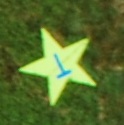
    Yellow Star photographed by ARC

    Yellow Star photographed by ARC

    The method begins with a black and white image showing just the shape in question.  For this experiment, black and white images where created as test samples.  Additionally some flight imagery was processed to generate the needed black and white images.  For this example I will process the image below which has been cropped from an image that ARC captured during the competition run.

    % Read in the original image
    pout = imread(filename);
    K = rgb2gray(pout);
    % Create a black and white image of the target
    K = rgb2gray(pout);
    bw = im2bw(K, graythresh(getimage));
    bw2 = imfill(bw,'holes');

    The above code works effectively on this image to create the needed bw image, however this code will not work on all targets.  Sharp variations in the background and certain target color combinations can ruin the data.  This issue was not further explored because the purpose of this experiment was not finding the targets, but identifying them.  It is assumed that the person using this program would provide a good bw target image.

    Using this image an outline of the target is created using the code:

    % Find the edge of the object
    K = edge(bw2,'sobel');
    [K, map] = gray2ind(K,2);

    Then the centroid of the object is found using the code:

    % Find the centroid
    s  = regionprops(bw2, 'centroid');
    centroids = cat(1, s.Centroid);

    With this data collected it is now possible to generate a signature of the target.  The signature is simply the distance from the centroid of the target to the outer edge.

    % Generate the target's signature
    dimen = size(K);
    counter = 1;
    for i=1:dimen(1)
        for k=1:dimen(2)
            if(K(i,k)~=0) % Found an edge point, save the data for this point
                    % Distance from centroid
                    signature(counter,1) = atan2((centroids(1,2)-i),(centroids(1,1)-k));
                    % Angle
                    signature(counter,2) = (sqrt((centroids(1,2)-i)^2+(centroids(1,1)-k)^2));
                    % Pixel position
                    signature(counter,3) = i;
                    signature(counter,4) = k;
                    counter = counter +1;
            end
        end
    end
    % Sort the signature data by angle
    signature = sortrows(signature);

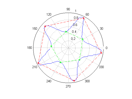
    From this point on, the challenge it to determine what the signature corresponds to.  For ease of viewing it is easiest to view the signal as plotted in polar coordinates.  The image below shows the signal generated by the preceding script as a blue line.
    data-T

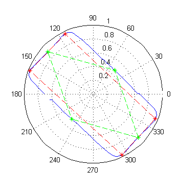
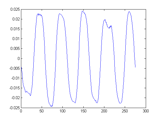
    The method used to process theses images tries to find certain features in the signature; in particular, local maximums and minimums.  Maximums indicate the location of an outside corner.  Minimums indicate inside corners or the midpoints of lines that run past the centroid.  A straight line will appear to get closer and closer to the centroid until it reaches a minimum and then begins to move away.  In the case of the star all minimums are inside corners, but in the rectangle shown below, all minimums are the result of lines passing by the centroid.
    data-L

    To find these points the instantaneous rate of change between each consecutive pair must first be calculated.  This produces the below chart shown in Cartesian coordinates.  Critical points are located at each point where the plot crosses the x axis.  This point can be easily located by checking for a sign change.
     

    diff-T

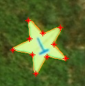
    Once the critical points have been located it is simply a matter of classifying the target.  Circles are filtered out first by looking for cases where the max and min of the signature are very close together. Next, the classifier discriminates based on the number of critical points.  This will be the final step for ovals and triangles.  For the other shapes a comparison of the  average maximum and minimum points values are compared.  Star like shapes will have a much greater difference than regular shapes.  Quadrilaterals undergo an additional check to compare the values of consecutive maximums.  A large difference will indicate a diamond shape.

    When run against a set of seven artificial targets, the method correctly identifies every shape.  Running against the real image set sees excellent results as well.  Moving forward it will be important to expand the data set to include more real images.  There are some enhancements to the current algorithm that may make it more robust.  It would also be interesting to explore the application of a neural net in solving the signature identification.   One final advantage to this algorithm is speed.  When just asked to determine the shape, the star image can be processed in less than half a second.
    processedT

    I’ve made the code available here as a download.  It requires the use of the Mathworks Image Processing Toolbox to work, which I don’t have anymore, so the code is provided as is without testing.

    TargetID
    NCSU Aerial Robotics Club 2010 Results

    Presented here are the results from NCSU ARC’s competition run at the 2010 AUVSI Student Unmanned Aerial Systems.

    sniper

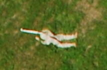
    Here is the picture we took of the emergent target given during flight.

    AUVSI2010-Message

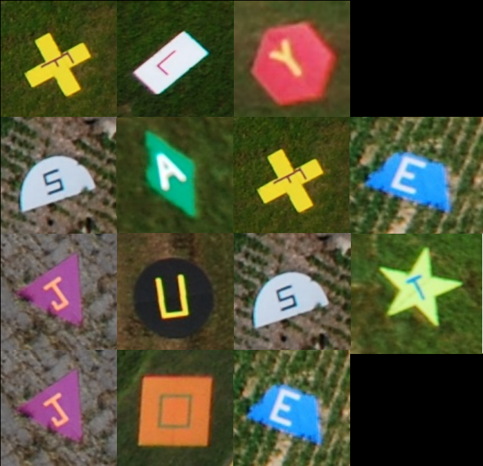
    Every year the targets in the field spell out a message.  This year the message was two part: “Fly safe” and  “Just Joe”.  The second phrase comes from Joe Brannan (The director of the competition) insisting that people just call him Joe instead of Joseph.  The graphic shown above was made using the imagery that we collected at competition with the exception of the “O” target.  The “O” target is provided by Utah State University.

    AUVSI SUAS 2010 Results

    Overall Results
    1. North Carolina State University
    2. Mississippi State University
    3. Embry Riddle Aeronautical University (Blackbird)
    4. Sherbrooke University (VAMUdes)
    5. University of California at San Diego
    Best Flight – North Carolina State University
    Best Journal – University of California at San Diego
    Best Oral Presentation – Embry-Riddle (Blackbird)
    Safety Award – Sherbrooke (VAMUdes)

    Prize Barrels
    Automatic Target Identification
    • University of Texas at Austin
    High Accuracy Target Finding
    • Rutgers University
    • Embry Riddle Aeronautical University (SOAR)
    • Florida International University
    Pop-up Target
    • Embry Riddle Aeronautical University (Blackbird)
    Actionable Intelligence
    • Utah State University
    • North Carolina State University
    Return top