Previously simulink was used to program Texas Intrument’s F28335 Delfino processor to simply command a servo through a sine wave. Since then two more important milestones have been covered; IMU communication and single channel PPM reading. In both cases the challenge is to correctly configure the existing simulink blocks.
Getting the IMU communication to work was extra challenging because both simulink and the IMU firmware needed to be set-up to communicate. The IMU is a sparkfun 9-dof board. This handy board reads three axises of acceleration, gyration, and magnetism. The board’s MCU contains an atmega328 with the arduino bootloader. Finally, there is software that can be downloaded to the board to combine the sensor data to get the roll, pitch, and yaw of the board. By adding the below output option to the output section of the code I can make it send its values in a binary form that the Delfino can read.
if PRINT_BINARY == 1
//Start Character
Serial.print(“S”);
unsigned char lowByte, highByte;
unsigned int val;
//Roll
val = ToDeg(roll)*100;
lowByte = (unsigned char)val;
highByte = (unsigned char)(val >> 8);
Serial.print(lowByte, BYTE);
Serial.print(highByte, BYTE);
//Pitch
val = ToDeg(pitch)*100;
lowByte = (unsigned char)val;
highByte = (unsigned char)(val >> 8);
Serial.print(lowByte, BYTE);
Serial.print(highByte, BYTE);
//Yaw
val = ToDeg(yaw)*100;
lowByte = (unsigned char)val;
highByte = (unsigned char)(val >> 8);
Serial.print(lowByte,BYTE);
Serial.print(highByte,BYTE);
//Ending Character
Serial.print(“E”);
For this to work the code must be set to only output this binary message and do so at 57600 baud. At higher speeds this board cannot keep up and will send erroneous data which will mess up simulink’s parsing.
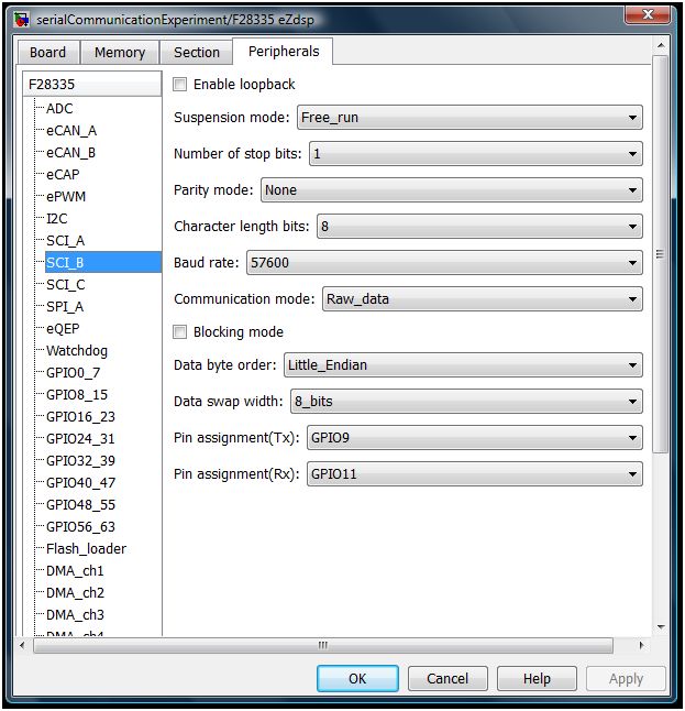
On the simulink side, the “Target Preferences block” (In this case F28335 eZdsp) needs to be configured as shown below.

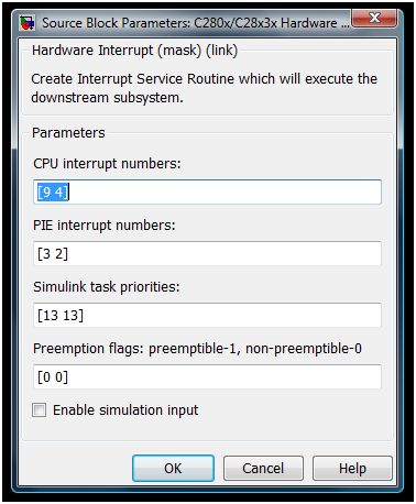
The Standard Communication Interface (SCI) module is placed inside of a function which is called by the interrupt handler. In simulink the top level of the program will look like below. The demux block after the interrupt block allows the IMU and PWM read to both use the interrupt block and still be called at the correct time. This is done because each simulink model may only contain a single “Hardware Interrupt” block. The Interrupt is then configured to look like the below:
 The first number in each field is related to the SCI interrupt while the second number in each field is for the PPM reader.
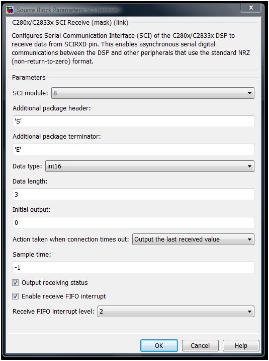
The inside of the function includes the SCI module as well as an example use of the data and a GPIO to warn of errors.
The SCI module should be configured as shown below.


