UAV CMOS Distortion

Using unmanned vehicles to capture aerial images is likely the most common use for these platforms.  The imaging system on these vehicles often uses a CMOS image sensor thanks to their relatively low-cost and wide spread use in most DSLR cameras.  One challenge of these sensors is that they can be susceptible to rolling shutter distortion.  The final result can vary between an image distorted beyond any usability and being imperceptible.

Webcam

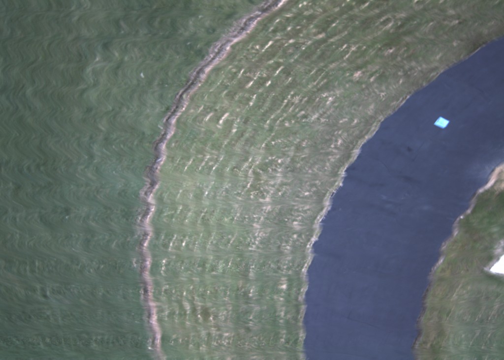
In this first example a Logitech Webcam Pro 9000 was attach to a Beaglebone black which would continuously take snapshots.  The imagery system was mounted on a 25 pound fixed wing aircraft with a gas engine.  From the photo it is clear that, due to the slowness of the capture, the image is largely unusable.

Bad distortion from web camera

Bad distortion from web camera.


Go-Pro

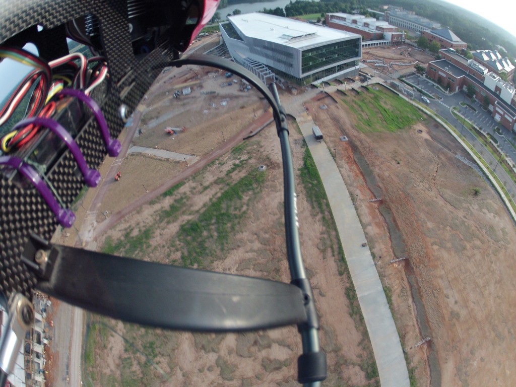
In another experiment a GoPro was mounted to the side of an electric helicopter.  The image here is much more usable and the distortion may not even be obvious with the exception of the landing gear in the foreground.  This highlights one of the dangers of this kind of distortion.  While the distortion may sometimes be very obvious, it may also be very subtle in the image.


Go-Pro mounted on a helicopter showing CMOS distortion on the landing gear


IDS Camera

While the camera and its settings play an important role in determining the effect of rolling shutter, the mount and vehicle dynamics can also have a dramatic effect.  In this case, the same camera with similar settings was mounted on a gas powered helicopter and then a gas powered fixed wing aircraft.

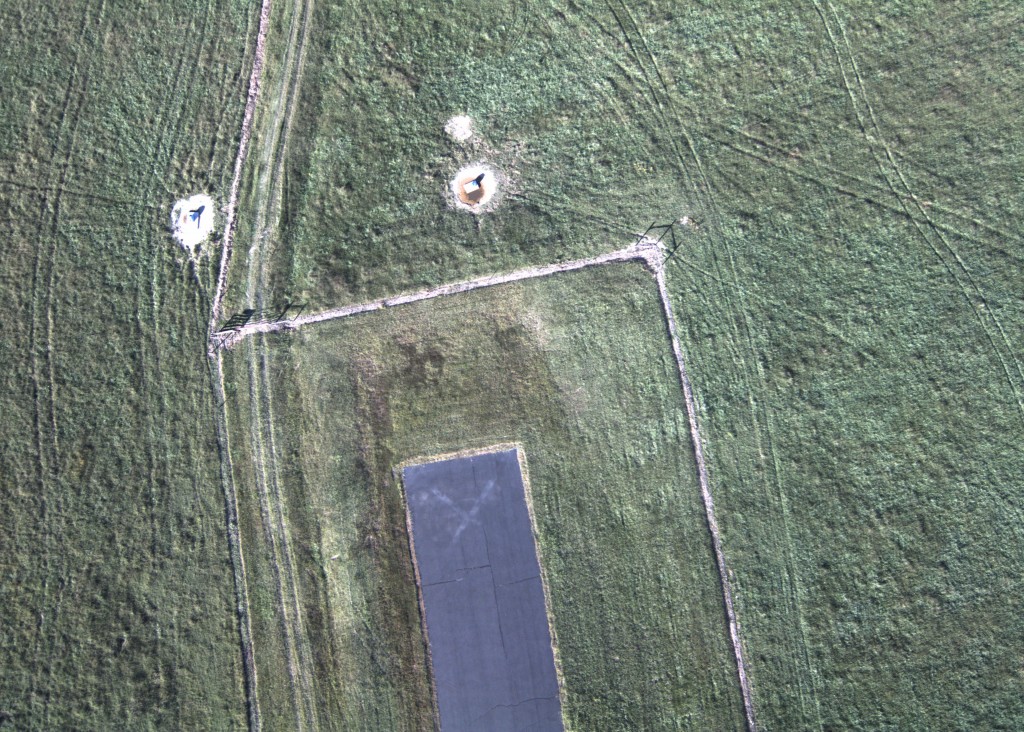
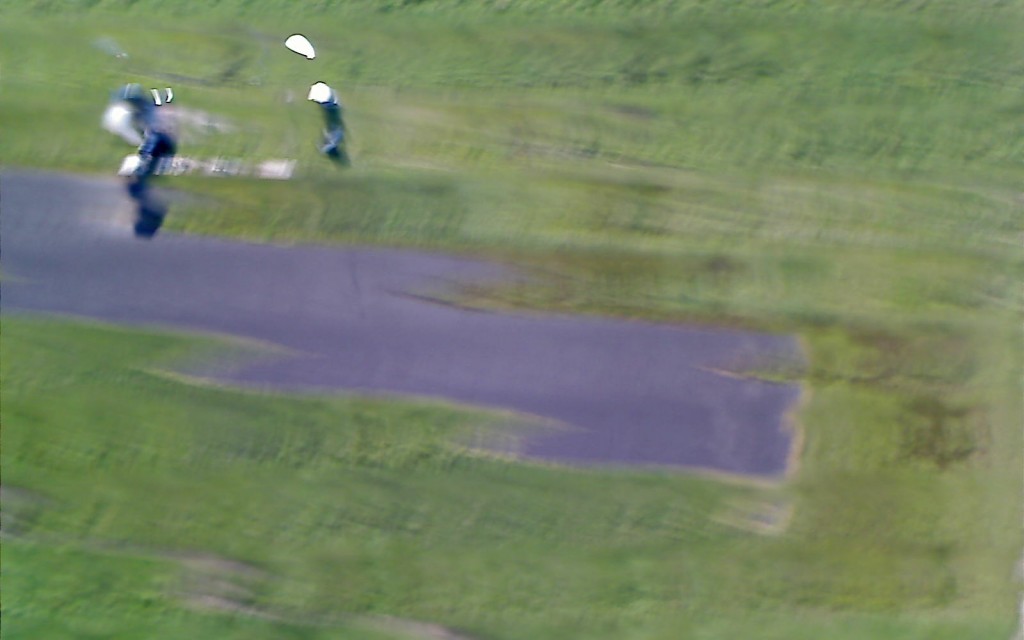
The helicopter was then flown through an aggressive set of maneuvers will the camera was capturing photos.  The camera was mounted directly to the helicopter frame with minimal vibration damping.  In the image there are two sources of distortion obvious.  Firstly, the straight runway now appears to arc up to the right.  This is a result of the rapid yawing of the helicopter during the capture.  The second source of distortion is obvious in the grass, fence, and edges of the photo.  This higher frequency distortion is a result of the helicopter vibration as a result of the rotor.

Helicopter Test

When the camera was mounted to the fixed-wing aircraft, the image that is captured is substantially better.  There is no obvious distortion as a result of the rolling shutter.  The slower dynamics of the fixed wing aircraft flying straight, level, and steady keep the runway straight.  The lower vibration levels of the aircraft and the addition of a vibration isolated mount removes the second source of distortion.  It bears mentioning that differences in the color quality of the image may also be influenced by difference in sunlight between the two flights.

IDS Camera mounted on a fixed wing aircraft

The effects of rolling shutter on aerial imagery can be quite severe, but are not insurmountable.  Being conscious of these effects can help of when evaluating the camera hardware, sensors, mounting and vehicle dynamics which all feed into determining the final quality of the image.

Matlab Central

The Aerospace Design Toolbox is now available on Matlab Central.  This release includes examples on how to use the various functions to integrate with XFoil, AVL, and more.

Aerospace Design Toolbox

I’ve recently switched to using Github for my open source projects.  As apart of this transition, I’ve been restructuring some of my old code.  This has lead to the creation of the aerospace-design-toolbox (ADT).

This Matlab toolbox is built from the Mavl code base.  The biggest difference between the two is scope.  While Mavl was designed to address the full scope of the design process from modeling to analysis, the ADT simply supports loading data from other aerospace software into Matlab.  Currently the ADT reads output files from AVL and Xfoil.  It can additionally read prop data in the format used by the UIUC propeller database.  For more information on what is and isn’t supported please see the README.m file in the repository.

At this time the toolbox is just a set of utility functions.  In the near term development will focus on converting the code into a standard toolbox that will integrate better with Matlab.

2012 AUVSI USUAS Results

The 10th annual Undergraduate Student Unmanned Aerial Systems competition hosted by AUVSI’s seafarer chapter concluded last week.  Teams from across the United States, Canada, India, and Turkey converged on Webster naval airfield for several days of autonomous competition.

Final standings

  1. Universite de Sherbrooke
  2. Embry-Riddle (UARE)
  3. California State at Northridge
  4. Delhi Technical University
  5. Cornell University
  6. North Carolina State University
Best Journal – University of Texas at Austin
Best Oral Brief – Kansas State University
Best Mission – Universite de Sherbrooke

 Autopilots

Listed here are some of the autopilots used by various schools.  If you know what autopilots any other schools were using please comment below.

Piccolo

  • North Carolina State University
  • Mississippi University
  • Kansas State University
  • Kansas State University (Pomona)
  • Cornell University
  • New Delhi University

Papparazzi

  • Universite de Sherbrooke
Micropilot
  • Great Mills High School
Custom
  • Utah State (Rotary)

Ardupilot

  • Rutgers University
  • Embry Riddle Prescott

3D Laser Cutting With a 2D System

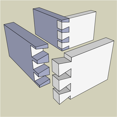
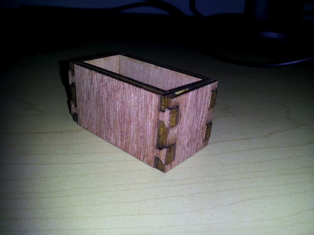
A typical laser cutter can make a precise 2D cut.  With rastering it is possible to etch the surface to add labeling.  However if the power of the laser can be finely controlled it is possible to make engineered depth cuts such as trenches or angled slopes.  This allows for laser cutting complex geometries such as a dovetail joint.

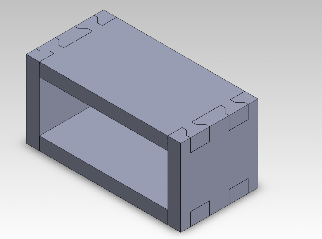
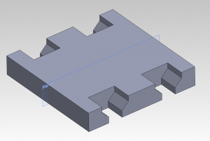
For this experiment a simple dovetail jointed box was modeled in Solidworks.

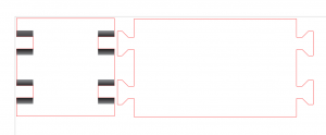
Although the long size of the box can be cut using typical methods, the end plates cannot.

Both parts where placed into a solidworks drawing which was then exported to *.pdf.  This was then imported into Corel Draw 5.  The initial drawings appeared as shown below.

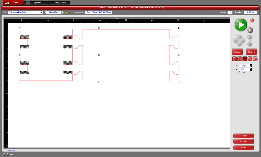
The lines to be cut were converted to “hairline” and RGB code <255,0,0>.  The Raster layer is defined by the gray-scale where back is 100% and white is 0%.  The power of the laser at 100% is set in the printer’s cut settings when the part is ready to be printed.  In this case, a gradient was drawn into the areas needing a depth cut.  The gradient allows for an angled cut between two particular depths.  The colors used and the number of passes to be completed were determined using a sort of look-up table.

Before this experiment, a set of colored squares were rastered into a material sample.  This was then repeated with two and three passses.  When selecting colors for the end plate cutting, the row that could reach the proper depth was selected.  In this case, the three-passes row was used with black at one end and a dark grey at the other.  This would result in a cut that was three black passes deep at one end and three dark-grey passes at the other.


Shown in the laser cutting software below, the final design was then sent to the laser. For the first two passes, the vector cutting was set to be skipped.  This allowed the depth cutting to be finished before the laser cut out the final outline.

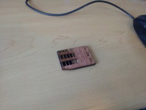
Finally the parts were removed from the laser cutter and the box shown below was assembled.  Two notable characteristics of the unglued box are its strength and its ease of assembly.  Even without glue the box doesn’t deform and tends to hold its shape.  Assembly was easier than just a tabbed box because once a joint was put together it had limited degrees of freedom about which to move.

Although this method can be time-consuming to setup, the final result creates good joints useful in engineered parts.

3D Printed Plug

In the process of manufacturing a senior design aircraft, a plug is used to create a negative mold on which aircraft fuselage skins can be laid up.  When the 2010-2011 senior design groups fabricated fuselage plugs, it was a lengthy process involving foam, plywood, fiberglass, epoxy, bondo, spackle, and an incredible amount of sanding.

This year a new method was tried with the intent of reducing the time required to manufacture the plug and allow for more complex geometric shapes to be used.  The availability of cheap rapid prototyping machines made this possible.  For this experiment the Ultimaker 3D printer in the Entrepreneurship Garage was used.  Based on previous experiments, PLA was used as the printed material.  North Carolina State University’s Aerospace Engineering Senior Design teams 3 and 4 participated in the experiment and provided the labor to integrate the printed parts into their aircraft plugs.

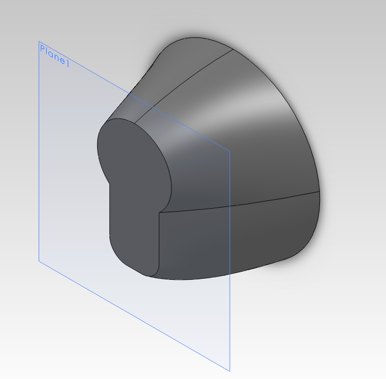
During the fall semester, the seniors designed the fuselage in solidworks.  The designs used a section of off-the-shelf PVC tubing as the main body with a nose cone and tail cone on either end to create the plug.  The nose and tail cones were modeled as separate parts and exported to *.STL format.

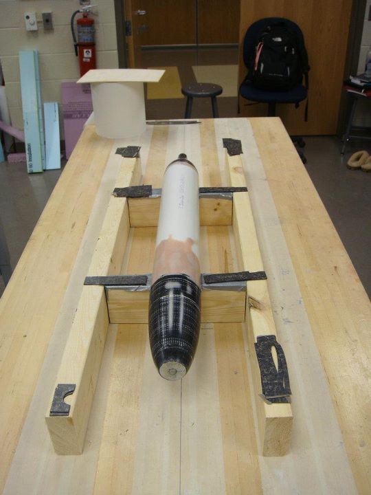
Team 3's Nose Cone

The UltireplicatorG software was then used to “slice” the model and create a GCODE instructions that the 3D printer could use.  In total, four parts were to be printed for the two teams.  Over the course of the printing a number of settings were experimented with.  The best results came when the solidworks models were simple solid objects with no shelling.  The slicer was then configured to print the object with zero infill and walls 3 layers thick.  This gave an object that was fast to print, but still rigid enough to be usable.  The final thickness of the wall was roughly 2-3 millimeters.

As this tail cone was being printed the extruder failed leaving several weak layers.

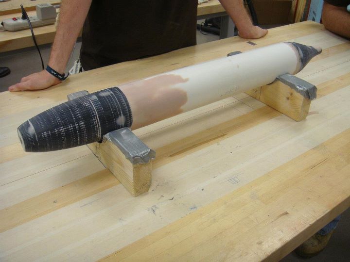
Once the printing was complete the seniors took over the process.  First an internal frame was cut to support, center, and join the cone to the PVC pipe.  The cone was then filled with plaster of paris to support the surface. Bondo and spackle were then applied to the surface to fill any cracks. Team 4 also added a shaft that stuck out the end of the mold.  This was then attached to a jury-rigged lathe.  The shaft was removed and sanded smooth once its purpose was served.

Rough sanded plug

After hours of hard work the final plugs were completed.  The final sanded surface is so smooth that reflections are clearly seen on its surface.

Final plug

With the plugs complete the teams used wax and PVA to prepare the plug for the mold layup.  While team 4 did not have any trouble getting the plug out of the completed mold, team 3 did have some difficulties.  However, these difficulties have been attributed to the waxing and PVA processes and not the 3D printed PLA material.

Overall the experiment was successful in its goals of reducing time to create the plug and allowing for the creating of complex geometries.  In particular, sanding was reduced since only the final surface was sanded.  In the old process, sanding had to be done on the foam surface, fiberglass surface, and the painted surface all of which took time.  Additionally, the geometries would have been difficult to create by other methods. While team 4’s radially symmetric cones could have been created on a lathe, team3’s cones could not.  The success of this method should serve as a stepping stone for future designed using more complicated geometries.

Laser Cut Settings

Finding just the right settings for a laser cutter can be a time consuming guess and check process.  Additionally, using a calibration technique, such as the one detailed here, adds more time to the process of getting parts cut.  To ease this process here are the settings I use when cutting with a 60 watt Universal Laser Systems machine.

formica (add 0.003″ contour): Used to create smooth airfoil shapes.  The laser file does not store the z height settings.  You will need to turn on the z-axis and set a height of 0.025″.

Matlab AVL Control

%% Create run file
%Open the file with write permission
fid = fopen(strcat(basename,’.run’), ‘w’);
%Load the AVL definition of the aircraft
fprintf(fid, ‘LOAD %sn’, strcat(filename,’.avl’));
%Load mass parameters
fprintf(fid, ‘MASS %sn’, strcat(filename,’.mass’));
fprintf(fid, ‘MSETn’);
%Change this parameter to set which run cases to apply
fprintf(fid, ‘%in’,   0);
%Disable Graphics
fprintf(fid, ‘PLOPngnn’);
%Open the OPER menu
fprintf(fid, ‘%sn’,   ‘OPER’);
%Define the run case
fprintf(fid, ‘c1n’,   ‘c1’);
fprintf(fid, ‘v %6.4fn’,velocity);
fprintf(fid, ‘n’);
%Options for trimming
%fprintf(fid, ‘%sn’,   ‘d1 rm 0’);
%fprintf(fid, ‘%sn’,   ‘d2 pm 0’);
%Run the Case
fprintf(fid, ‘%sn’,   ‘x’);
%Save the st data
fprintf(fid, ‘%sn’,   ‘st’);
fprintf(fid, ‘%s%sn’,basename,’.st’);
%Save the sb data
fprintf(fid, ‘%sn’,   ‘sb’);
fprintf(fid, ‘%s%sn’,basename,’.sb’);
%Drop out of OPER menu
fprintf(fid, ‘%sn’,   ”);
%Switch to MODE menu
fprintf(fid, ‘%sn’,   ‘MODE’);
fprintf(fid, ‘%sn’,   ‘n’);
%Save the eigenvalue data
fprintf(fid, ‘%sn’,   ‘w’);
fprintf(fid, ‘%s%sn’, basename,’.eig’);   %File to save to
%Exit MODE Menu
fprintf(fid, ‘n’);
%Quit Program
fprintf(fid, ‘Quitn’);
%Close File
fclose(fid);

Mark Drela’s Athena Vortex Lattice (AVL)  program is a powerful tool for aerodynamic analysis.  Automating AVL runs using Matlab not only saves time, but eliminates human error when plugging through a large range of run cases.  In combination with tools for parsing the results and editing the models this automation may also enable design methods such as genetic algorithms and other iterative approaches.

Included below is a zip file containing the example script detailed here as well as a set of sample AVL files copied from the AVL source directory.  You will need to download AVL yourself and place the executable in the unzipped folder with the other files. Alternately, you may change the path to the avl executable in the last line of the script.  This tutorial was tested against avl 3.27.  Version 3.16 may have issues.

runAVL

Creating the run file

The run file to be created is simply a batch script that will be fed into AVL.  This will cause AVL to act as though the commands in the batch file are being typed in by a user.  The process begins by creating a blank file to put the batch script in.

%% Create run file %Open the file with write permission fid = fopen('.allegro.run', 'w');

Once this is complete, each line of the batch script is “printed” to the file by the fprintf command.  First, the aircraft’s avl and mass file are loaded into AVL.  The MSET command is executed to apply the mass parameters to all the run cases.  Then graphics are disabled to allow the program to run silently in the background.

%Load the AVL definition of the aircraft
fprintf(fid, 'LOAD %s\n', strcat(filename,'.avl'));

%Load mass parameters
fprintf(fid, 'MASS %s\n', strcat(filename,'.mass'));
fprintf(fid, 'MSET\n');
%Change this parameter to set which run cases to apply
fprintf(fid, '%i\n',   0); 

%Disable Graphics
fprintf(fid, 'PLOP\ng\n\n');

Once the setup is complete, the run case is defined and executed.  In this instance the C1 command is used to “set level or banked  horizontal flight constraints”.  The velocity is then set.  Depending on the purpose of the run case you may also use commands such as commented out under “Options for trimming”.  The case is then run using the X command.

%Open the OPER menu
fprintf(fid, '%s\n',   'OPER');   

%Define the run case
fprintf(fid, 'c1\n',   'c1');
fprintf(fid, 'v %6.4f\n',velocity);
fprintf(fid, '\n');

%Options for trimming %fprintf(fid, '%sn', 'd1 rm 0'); %Set surface 1 so rolling moment is 0 %fprintf(fid, '%sn', 'd2 pm 0'); %Set surface 2 so pitching moment is 0

%Run the Case
fprintf(fid, '%s\n',   'x');

Once the run is complete, the desired data in the OPER menu is saved to files for post analysis.  This example shows how to save the stability derivatives (ST) and body-axis derivatives (SB) data.  Other data that can be saved off in a similar fashion as shown below include:

  • ST  stability derivatives
  • SB  body-axis derivatives
  • RE  reference quantities
  • FT  total   forces
  • FN  surface forces
  • FS  strip   forces
  • FE  element forces
  • VM  strip shear,moment
  • HM  hinge moments
%Save the st data
fprintf(fid, '%s\n',   'st');
fprintf(fid, '%s%s\n',basename,'.st');
%Save the sb data
fprintf(fid, '%s\n',   'sb');
fprintf(fid, '%s%s\n',basename,'.sb');
%Drop out of OPER menu
fprintf(fid, '%s\n',   '');

Other data may also be obtained by leaving the OPER menu and entering the MODE menu.  This eigenvalue data can be useful for analyzing an aircraft’s stability.

%Switch to MODE menu
fprintf(fid, '%s\n',   'MODE');
fprintf(fid, '%s\n',   'n');
%Save the eigenvalue data
fprintf(fid, '%s\n',   'w');
fprintf(fid, '%s%s\n', basename,'.eig');   %File to save to

%Exit MODE Menu
fprintf(fid, '\n');

Once all the desired runs have been computed and saved, it is important to use the return key character ‘n’ to return to the top level menu before issuing the Quit command to exit out of AVL and back to the command line. With the script complete the batch script file is closed.

%Quit Program
fprintf(fid, 'Quit\n'); 

%Close File
fclose(fid);

Executing the script

Files whose names conflict with new files to be generated should be moved out of the target directory or deleted before running the script.

[status,result] =dos(strcat('del ','allegro.st'));

Execution of the script from matlab is acheived by simply using the below command.  The dos command tells matlab to execute the string argument on the command line.  The instruction tells the OS feed the allegro.run file in the local directory to the avl executable at the absolute address shown.  The dos function also returns status and result data.  The status variable will get the final return state of the execution, nominally a 0 unless the program crashed.  The result variable will contain all the text that would have been printed to the screen if executed from the command line.

[status,result] = dos('C:avl.exe < .allegro.run');

With this complete the batch script will have successfully executed your run case or will have crashed.  To debug your batch script it is helpful to look through the result variable’s data.  Also helpful is to manually type in a script so that you can see more easily what the program is trying to do.
Rapid Prototyping Nose Cones

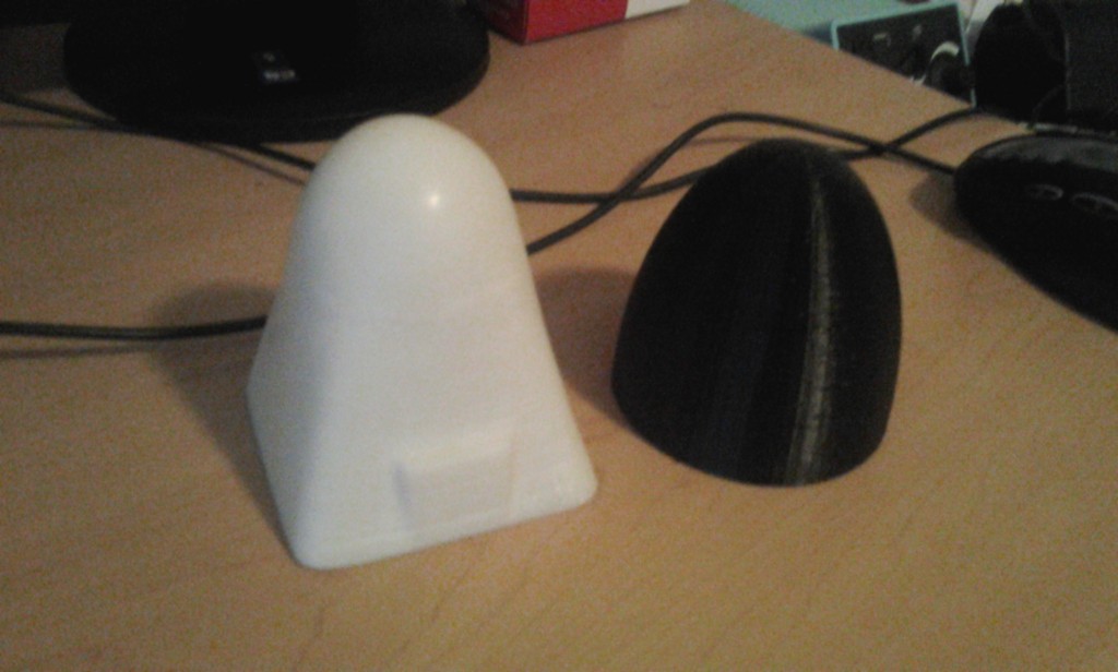
One of the compelling reasons for buying a Reprap Mondo was the potential for printing aircraft molds and parts.   Keeping with this goal, the Reprap Mondo was used to print the nose cone shown below in white ABS.  Its basic geometry is based on my senior design aircraft’s nose.  Recently I obtained access to an Ultimaker via the Entrepreneurship Initiative’s Garage.  Using the Ultimaker an elliptical nose cone was printed in black PLA.

Printed Nose Cones

Printed Nose Cones

The white nose cone pictured has been sanded and polished while the black cone is raw off the printer.  Overall the surface finish was similar between the two pieces.  Both did suffer from surface defects including an instance on both prints when their respective printers stopped extruding for a moment causing a large defect.  The white ABS cone did have the advantage that most of its defects were positive allowing them to be sanded while the black PLA cone has regular pit defects.  This is attributed to the ultimaker switching from the outer shell to the inner surface at such high speed.

Since the quality of the finished parts is rather close, the biggest difference between them is the time it took to print.  While the Mondo spent 6 hours printing the ABS piece, the Ultimaker only took 1.5 hours.  The comparison is not the best since the objects are distinctly different, but the conclusion stands that the Ultimaker is much much faster than the Mondo.

The difference in the materials is not particularly apparent in the final products.  Both parts are rigid, easy to sand, and fairly indestructible.  Since the parts are intended for use as molds, the strength to weight consideration is not present as it would be in flyable parts.  The important difference during this experiment was the ease of printing.  To prevent the ABS cone from warping it needed a heated bed, a heat gun, and super glue to ensure that it stayed on the platform.  The PLA cone needed none of this and printed just fine.

The one advantage that the Mondo has over the Ultimaker is its larger print volume.  However, the difficulties of printing in ABS have precluding actually using that greater volume.  Based on this, further work shall focus on the use of PLA as the material of choice.

Importing Airfoils into Solidworks

Solidworks is a great CAD program that can be useful in the design of aircraft.  However, one difficulty can be importing complex curves such as airfoils.  The challenge lies primarily in formatting the data such that solidworks can import it with its curves menu.  An example of properly formatted data is included below.

HS130

For data to be imported the file must contain X, Y, and Z coordinates in a tab-delimited file with no header.  Units may be included immediately after the number (“in” and “m” have been tested to work).  This can be accomplished with with an excel file by exporting the data as a tab-delimited file.  It may also be accomplished using the below python script to parse the data.  The script accepts arguements for filename (“-f” or “filename=”) and chord length in inches (“-c” or “chord=” ).  The airfoil data should be in a space-delimited file format.

foil2sldcrv

Once the data is ready to be loaded the process is fairly straight forward.

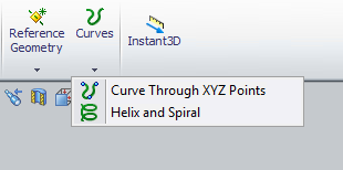
Solidworks Curves Menu

Solidworks Curves Menu

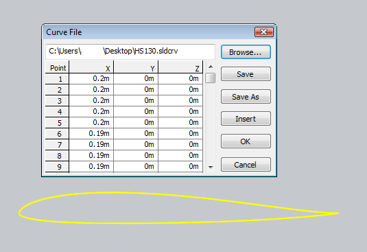
Clicking on the “Curve Through XZY Points” brings up a window from which the user may browse for a file containing their points.  This then allows the user to click “Browser” and select the file to import.

Curves menu with a sample airfoil loaded

Curves menu with a sample airfoil loaded

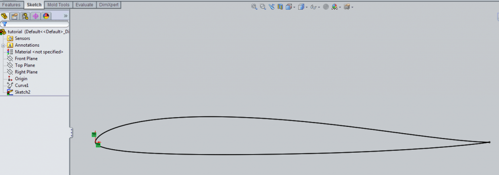
Once this has been completed a “Curve” object is added to the Feature Manager, typically found on the left side of the screen.  The user may then create a sketch incorporating the airfoil data by using “Convert Entities” and then selecting the airfoil curve using the Feature Manager.  It is also advisable to right-click the curve on the Feature Manager and select “hide” so as to avoid future confusion.

Imported airfoil data with Feature Manager at right

Imported airfoil data with Feature Manager at right

Deleting the the “On Edge” constraints (the small green squares shown in the above image) will allow the airfoil to be moved and scaled as desired.  This may create a second airfoil to appear that is attached at the same ending point.  Simply deleting the second outline seems to be the easiest way to fix the problem.  Once the sketch is free to move you can then constrain it as needed.

Constrained Airfoil

Constrained Airfoil

Return top