3D Laser Cutting With a 2D System
- May 29th, 2012
- Write comment
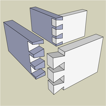
A typical laser cutter can make a precise 2D cut. With rastering it is possible to etch the surface to add labeling. However if the power of the laser can be finely controlled it is possible to make engineered depth cuts such as trenches or angled slopes. This allows for laser cutting complex geometries such as a dovetail joint.
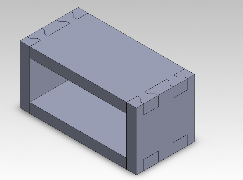
For this experiment a simple dovetail jointed box was modeled in Solidworks.
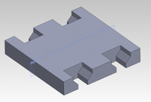
Although the long size of the box can be cut using typical methods, the end plates cannot.
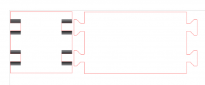
Both parts where placed into a solidworks drawing which was then exported to *.pdf. This was then imported into Corel Draw 5. The initial drawings appeared as shown below.
The lines to be cut were converted to “hairline” and RGB code <255,0,0>. The Raster layer is defined by the gray-scale where back is 100% and white is 0%. The power of the laser at 100% is set in the printer’s cut settings when the part is ready to be printed. In this case, a gradient was drawn into the areas needing a depth cut. The gradient allows for an angled cut between two particular depths. The colors used and the number of passes to be completed were determined using a sort of look-up table.
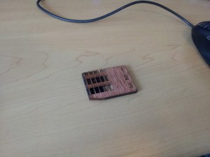
Before this experiment, a set of colored squares were rastered into a material sample. This was then repeated with two and three passses. When selecting colors for the end plate cutting, the row that could reach the proper depth was selected. In this case, the three-passes row was used with black at one end and a dark grey at the other. This would result in a cut that was three black passes deep at one end and three dark-grey passes at the other.
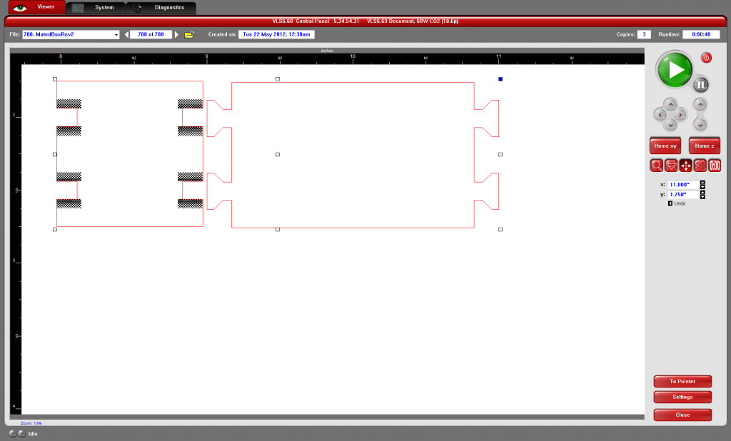
Shown in the laser cutting software below, the final design was then sent to the laser. For the first two passes, the vector cutting was set to be skipped. This allowed the depth cutting to be finished before the laser cut out the final outline.
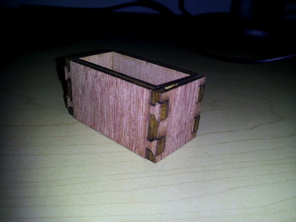
Finally the parts were removed from the laser cutter and the box shown below was assembled. Two notable characteristics of the unglued box are its strength and its ease of assembly. Even without glue the box doesn’t deform and tends to hold its shape. Assembly was easier than just a tabbed box because once a joint was put together it had limited degrees of freedom about which to move.
Although this method can be time-consuming to setup, the final result creates good joints useful in engineered parts.
