RepRap Mondo – Part 7 – Endstops

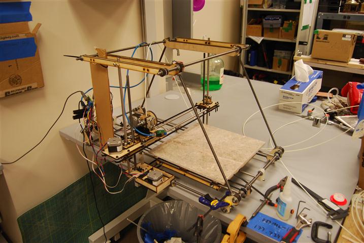
The RepRap Mondo’s mechanics are one of its strongest attributes, however in designing the machine it appears that the endstops were completely forgotten.  As a result of this and a complete lack of instructions, the locations and mounts for all the endstops shown are based only on our conjecture, but having run our machine for a while now we can confirm that these positions do work.

The cables that came with the endstops do not fit properly on the pins from the endstop.  As a result, they have a tendency to pop off.  We cut off the ends an soldered them directly to the contacts inside the end-stops.  These were exposed by cutting part of the end-stop enclosure off.

X end-stop

X end-stop

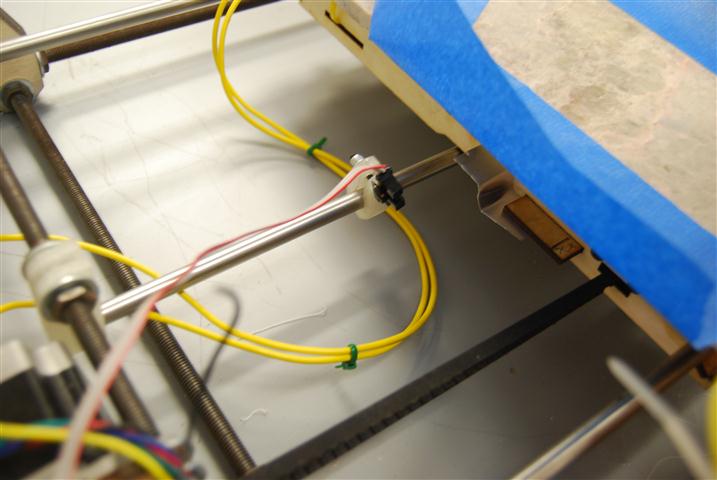
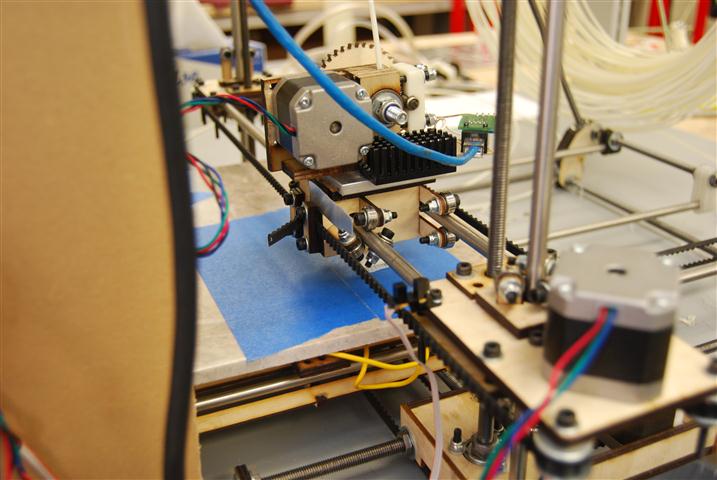
The X-axis end-stop sensor was mounted to an extra hole we conveniently found on the elevator assembly.  The kit ships with a piece of thin aluminum that we cut down to the size shown.  The belt clamp was loosened and the aluminum plate was slipped in.  On tightened down the clamp held the aluminum quite well.  There is a small angle cut into the bottom of the aluminum plate so that if it gets bumped down the angle will cause the piece to get pushed back up instead of being mangled.

Y End-stop

Y End-stop

The Y end-stop sensor mounts to a small RepRapped piece which slides over the Y axis smooth rods.  A bolt clamps the rod and holds the sensor.  A small piece of wood was glued to the bed to make a small shelf to mount the aluminum piece.  The Z-bend in the aluminum makes it easier to adjust.  The aluminum is super-glued to the bed frame shelf.  To clear the deck, the sensor is bent back at a slight angle.   It would probably also work to mount the sensor rotated 180 to avoid needing to tilt it.

The Y end-stop sensor is mounted so far forward in the above picture because our marble bed is currently 6 inches shorter than the warped 18″ bed that the kit shipped with.

Z End-stop

Z End-stop

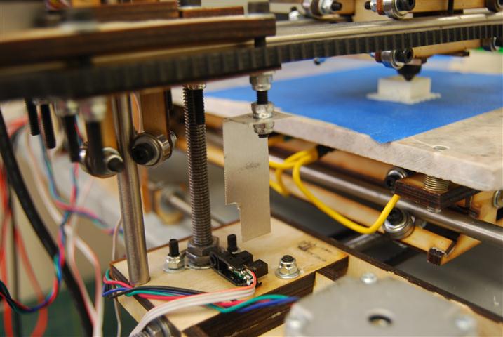
To mount the Z End-stop we glued the sensor on its side to the base of the elevator.  We then cut a hole in the aluminum piece and used lock-nuts to attach it to the bottom of one of the screws used int he elevator assembly.  This is the only end-stop mount that is finely adjustable and is so specifically because you will need to tune this axis the most.  Slight adjustments can make a big difference.
RepRap Mondo – Part 6 – The Bed

Aluminum Bed

The Mondo ships from Techzone with an aluminum bed.  The 18″ x 12″ bed comes with six holes for mounting to the base support.  Although the holes are nicely chamfered they did not include machine screws to go with the holes.  None of the screws that fit through the holes were flush with the bed either.  After hitting one of the bolt heads with the extruder nozzle we made a run to the hardware store to get a pack of 4-40 1″ screws with nuts.
Techzonecom warped metal bed

Techzonecom warped metal bed

With the proper screws in place we then set about leveling the bed.  Several hours later I discovered that the bed was badly warped such that no amount of tweaking would make it flat.  We measured a tip deflection of 3-4 mm near the ends which was a significant problem given that the layer thickness was 0.4 mm.  For a while we continued printing by restricting the build area to a three inch square near a corner we leveled relative to the head.

Glass Bed

This deficiency in the bed lead us to our first alternate bed made from 3mm glass, which turned out to be 2.3 mm when meaured with calipers.  The 18″ x 12″ glass bed was cut for us and only cost $5.  It was mounted on top of the aluminum bed by placing six blobs of “clear silicone, waterproof sealant” that we picked up from the hardware store.  We selected it based on its tolerance of heat up to 175 degrees Celsius which was above any of the temperatures we expected the bed to see.  Once the glass was set on the silicone we then shimmed and squished down the bed as needed to get it level.
Remains of the glass bed

Remains of the glass bed

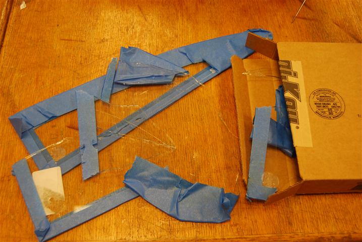
However, during later prints we found that heating the bed with a heat gun resulted in superior print quality with reduced warping.  Unlike the metal bed which nicely conducted the heat through out, the glass bed required that heat be applied locally at the printing area.  Although this arrangement worked for a while, as we tried to increase the local temperature the local heating eventually caused a crack to form across the bed starting from a chip on the edge.  The glass bed wasn’t destroyed at that point, but rather as we tried to get the glass bed off we had to resort to breaking the bed down into more manageable, albeit razor sharp, sections.

Marble Bed

It was at this point that the suggestion was made that we try a thin ceramic material used as a base material in thick film circuit deposition.  It was quickly determined that there was no local supplier and the material would be expensive.  However, 3/8″ granite and marble floor tiles are cheaply available at the local hardware store and come in 12″ and 18″ squares.  For this first experiment we purchased a 12″ marble tile for $2.28.
Marble bed installed

Marble bed installed

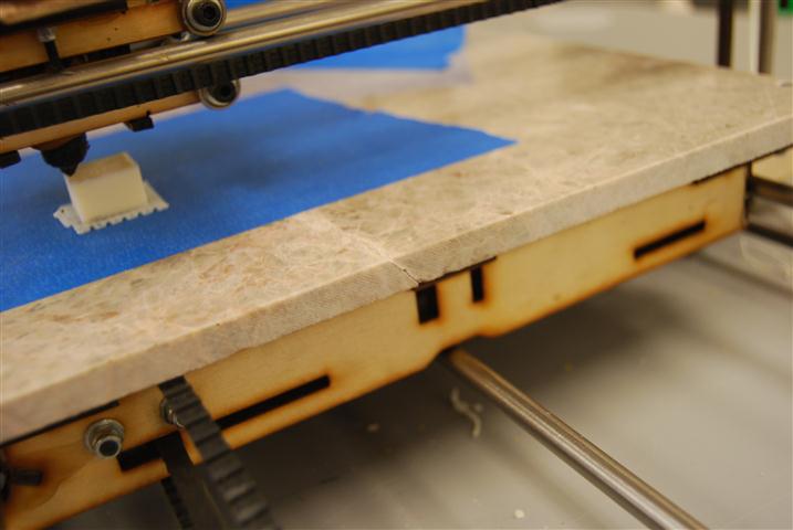
The marble bed has proven over the last week to be incredibly flat, durable, and gorgeous.  Mounting to the bed support was accomplished by drilling four holes with a tile bit set before then chamfering the holes with a larger bit.  It is also noteworthy that although this bed takes a while to heat up, once it is hot it tends to stay hot for an extended period of time.
The only problem he have had is in our selection of an individual tile. The tile that we selected had a natural crack running through it that was visible on both the top and bottom of the tile.  The crack is more obvious when the bed is heated up.  Despite this, once a printing surface is laid down, such as the painter’s tape shown, the crack has no effect on the usability of the surface.
A natural crack in the marble

A natural crack in the marble

Return top