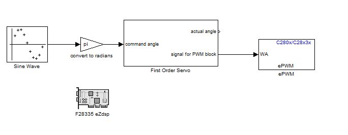
Servo Sin Wave

Automatic code generation is a powerful tool that when combined with Simulink promises important benefits to students and highly complicated applications alike.  Mathworks distributes an Arduino Blockset for Simulink.  The Arduino platform is a desirable to use because of its simple architecture and available hardware.  These hardware options include the ArdupilotMega (APM) which includes sensors and pinouts that will make it easier to integrate into a future aerial vehicle.

While the 2012a version only requires the base Matlab and Simulink packages, NCSU does not currently provide the 2012a version to students.  Instead the 2011a version was used since it was available.  It is not expected that there will be problems using the work done with 2011a in the 2012a release.

The base Arduino blockset includes blocks for Analog and Digital I/O as well as serial communication.  To take full advantage of the capabilites of the APM, additional blocks for SPI, I2C, PPM, and Servos are needed.  Development of a servo blocks has been the focus of this last week.

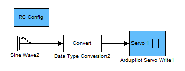
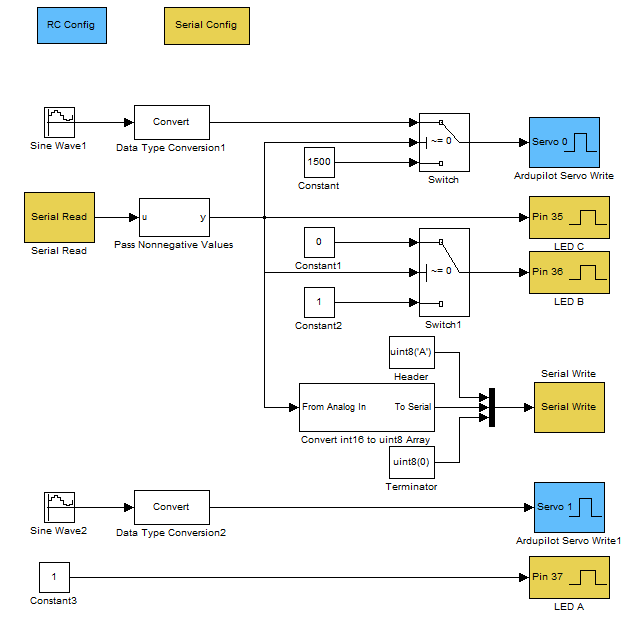
  The new blocks, shown in blue, allow for the configuration and control of servos attached to the APM.  An interesting note  is that although the APM only has 8 servo lines broken out on the side, there are an additional 3 lines (PL3, PB5, and PE3) that can be configured to output PWM commands. These lines are broken out from the APM base-board, but are not available on the sensor-shield “Oilpan”.

With just the blocks from the base, shown in yellow, and the new servo blocks it is already possible to access quite a few of the APM’s functions.  The demonstration program shown above commands two servos through a sin wave motion.  Data is read from the serial port allowing for the functionality of Servo 1 to be switched between sin wave and center position.
Making TI and Arduino Talk

Previously simulink was used to program Texas Intrument’s F28335 Delfino processor to simply command a servo through a sine wave.  Since then two more important milestones have been covered; IMU communication and single channel PPM reading.  In both cases the challenge is to correctly configure the existing simulink blocks.

Getting the IMU communication to work was extra challenging because both simulink and the IMU firmware needed to be set-up to communicate.  The IMU is a sparkfun 9-dof board.  This handy board reads three axises of acceleration, gyration, and magnetism.  The board’s MCU contains an atmega328 with the arduino bootloader.  Finally, there is software that can be downloaded to the board to combine the sensor data to get the roll, pitch, and yaw of the board.  By adding the below output option to the output section of the code I can make it send its values in a binary form that the Delfino can read.

if PRINT_BINARY == 1
//Start Character
Serial.print(“S”);
unsigned char lowByte, highByte;
unsigned int val;
//Roll
val = ToDeg(roll)*100;
lowByte = (unsigned char)val;
highByte = (unsigned char)(val >> 8);
Serial.print(lowByte, BYTE);
Serial.print(highByte, BYTE);
//Pitch
val = ToDeg(pitch)*100;
lowByte = (unsigned char)val;
highByte = (unsigned char)(val >> 8);
Serial.print(lowByte, BYTE);
Serial.print(highByte, BYTE);
//Yaw
val = ToDeg(yaw)*100;
lowByte = (unsigned char)val;
highByte = (unsigned char)(val >> 8);
Serial.print(lowByte,BYTE);
Serial.print(highByte,BYTE);
//Ending Character
Serial.print(“E”);

For this to work the code must be set to only output this binary message and do so at 57600 baud.  At higher speeds this board cannot keep up and will send erroneous data which will mess up simulink’s parsing.

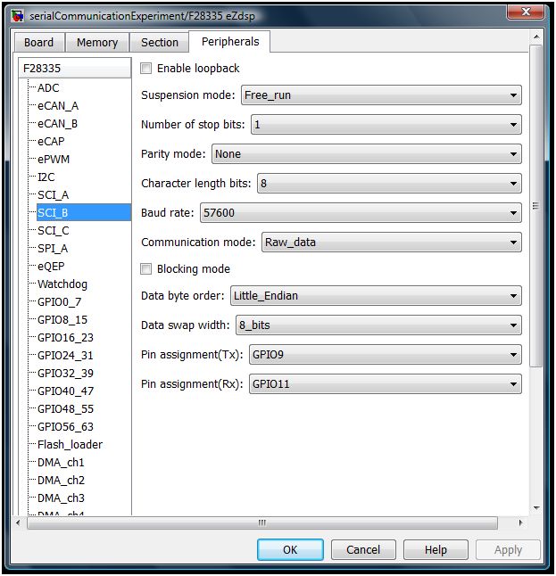
On the simulink side, the “Target Preferences block” (In this case F28335 eZdsp) needs to be configured as shown below.

F28335a

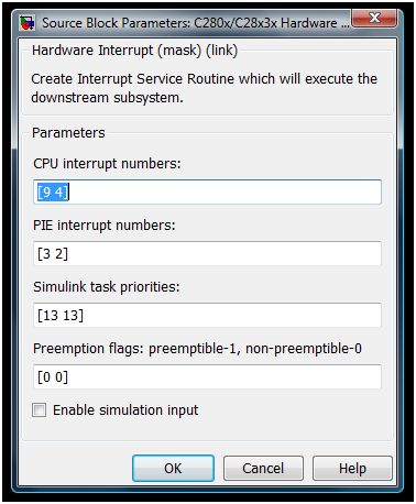
The Standard Communication Interface (SCI) module is placed inside of a function which is called by the interrupt handler.  In simulink the top level of the program will look like below.  The demux block after the interrupt block allows the IMU and PWM read to both use the interrupt block and still be called at the correct time.  This is done because each simulink model may only contain a single “Hardware Interrupt” block.headThe Interrupt is then configured to look like the below:

interruptThe first number in each field is related to the SCI interrupt while the second number in each field is for the PPM reader.

The inside of the function includes the SCI module as well as an example use of the data and a GPIO to warn of errors.imuTI

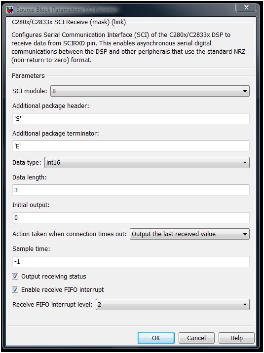
The SCI module should be configured as shown below.

F28335b

Simulink Hardware Servo Block

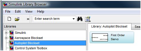
Simulink libraries perform complex functions and augment the capabilities of the Simulink software.  With libraries like the Aerospace Blockset, complex tasks (like creating a 6 dof simulator)  are greatly simplified.  As an exercise I started what I am calling the Autopilot Blockset.  The purpose of this library is to hold the blocks that connect the control system blocks to the hardware blocks.  Although right now the library might better be called the hardware servo library, the plan is to expand the library with blocks for telemetry packets and AHRS communication.

Autopilot_Library

Currently the library contains just the Servo block.  This block converts the angles used by a control system into a signal the hardware can use to command the physical servo.  In testing the block was used to smoothly command a servo through a 180 degree sweep using the below model.

ServoSweep

The servo block is configured through a menu that is shown by double-clicking on the servo block.  The angle commanded by the user will be the angle of the surface it is connected to if the pulse length limits and their angles are properly configured.  In a simple example the servo arm can be setup as the controlled surface by setting the limit angles to 90 and -90.  Regardless of the commanded angle the servo will not be commanded beyond the pulse length limits.  Because of this, an actual angle output is made available which provides the actual commanded position taking into account any truncation due to limits.

Return top