NCSU eGames Design and Prototype Challenge

The Entrepreneurship Initiative at NC State runs an annual competition called the eGames.  The games bring students together to compete in different entrepreneurship tasks.  This year I entered the “Design and Prototype Challenge” with a paper detailing the unmanned system that I am currently developing for a client.  Today I received an email that I have qualified to move on to the finalist presentations, so I’ll be presenting at the Entrepreneurship Expo on April 21.

Simple Necessities

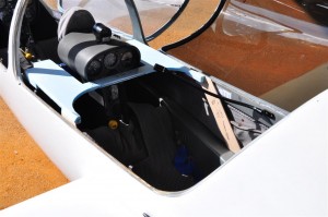
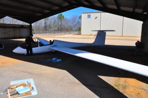
It is sometimes the case that even the most ambitious projects must start off by addressing the most simple of problems.   In this instance a laptop needed to be mounted in the Grobe glider shown below.  The person sitting in front of it also needed to maintain full access to the flight controls and be able to enter and leave the aircraft.

grobe

The Grobe

For this part of the project my role was to be a stand-in pilot as the desk’s support frame was fitted.  The completed frame model is shown below.  It is now being fiberglassed.

DSC_2898 (Medium)

Completed desk frame in the Grobe

Parting Plane Fabrication

Once the fuselage plug has been completed it may now be used as the basis for the fabrication of the fuselage molds.  This process starts with the fabrication of a parting plane.  The parting plane, as its name implies, is used to form the plane between the two halves of the fiberglass mold.  It will only be used for creating the first half of the mold.  The second half will be laid up against the first half.

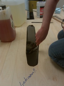
To create the parting plane a rough cut slightly smaller than the body is made with a miter saw into a plywood piece.  This is then carefully sanded down so that the fuselage plug just fits.

parting_plane

Rough parting plane being sanded

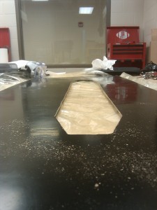
Once the hole is finished, the entire board is sanded, painted, sanded again, and then waxed.  Once this is complete, the parting plane should have an almost mirror-like finish to it.

parting_plane

Mirror finish on completed parting plane

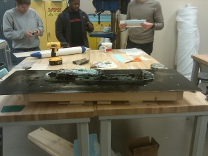
To support the parting plane and hold the plug halfway through the hole, a sub-structure is created under the parting plane.  It is important to ensure that holes drilled will be beyond the area over which fiberglass will be laid for the mold.

parting_plane_substructure

Parting plane with sub-structure and plug

This is not an echo

X-CTU

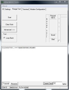
Digi, the manufacturer of zigbees, provides a useful tool for configuring and testing the units.  One feature of this tool is a “Range Test”.  The test is based on the concept of a loop back.  A certain packet is sent from the local zigbee to a remote zigbee.  The remote zigbee then echos the packet back.  By comparing the packet sent to the packet received errors can be detected.  The inclusion of an RSSI measurement makes the tool even more useful.

However, when running the tool with the Ardupilot Mega (v1.02) code running a range test the results returned where abysmal.  An investigation into the code revealed the code shown below.  The critical section is shown in bold where the author choose to copy the default packet into the code and simply transmit it every quarter of a second.  The abysmal results from running the range test were caused by the radios being configured at a different baud rate than the author had assumed.  Additionally, when running the rssi test a delay was introduced which resulted in the tool seeing terrible packet corruption.

test_xbee(uint8_t argc, const Menu::arg *argv)
{
	...
	while(1){
		delay(250);
		// Timeout set high enough for X-CTU RSSI Calc over XBee @ 115200
		Serial3.printf_P(PSTR("0123456789:;<=>?@ABCDEFGHIJKLMNO"));
		//Serial.print("X");
		// Default 32bit data from X-CTU Range Test
		if(Serial.available() > 0){
			return (0);
		}
	}
}

Shown here is a simple implementation of an actual loop back.  This change has been adopted by the Ardupilot project and should be available in the next release.

test_xbee(uint8_t argc, const Menu::arg *argv)
{
	...
	while(1){
                int incomingByte;
                if(Serial3.available()>0){
                      incomingByte = Serial3.read();
                      Serial3.print(incomingByte,byte);
                }
		if(Serial.available() > 0){
			return (0);
		}
	}
}

Fuselage Plug Fabrication

Since the beginning of the semester we have made significant strides forward in building our senior design aircraft.  This post will focus on the fabrication of the fuselage plug.  The goal is to produce the fuselage geometry such that it may be used to create molds from which the actual aircraft skins may then be manufactured.
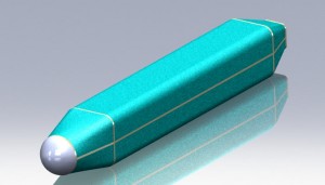
Render of the base plug to be created.

Render of the base plug to be created.

The core of the plug was made using a combination of foam and thin plywood.  As shown below, the plywood bulkhead serve to create the profile shape of the body while the lengthwise pieces of plywood serve to keep the bulkheads positioned and aligned correctly.  Foam blocks where then glued into the spaces and cut using a hot wire bow and a steady hand.  Once cut, the bulkheads are shimmed as needed and the gaps filled with epoxy.
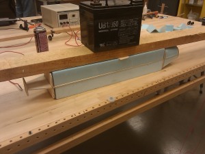
Early stage of plug fabrication

Early stage of plug fabrication

To create the spherical nose of the aircraft, a foam ball from a crafts store was shaved down on a sanding belt until the correct circumference was had.  This was then epoxied to the front bulkhead.  Once all the foam was in place, the remaining seams and imperfections were covered in spackle and sanded down.
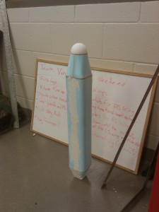
Plug covered in spackel ready for sanding

Plug covered in spackel ready for sanding

Next, the wing saddle is cut out of the plug.  This wing will sit such that the leading edge and trailing edge will sit flush with the body.  The cut is accomplished by clamping a plywood profile of the bottom of the wing to the plug.  Clamps, screws, and a plywood offset piece all work to keep the profile in place.  Again the cut is completed with a hot wire bow and a steady hand.
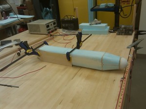
wing_saddle_cut

Plug ready for wing saddle to be cut

The last remaining feature to be added was the ventilation scope.  The basic shaped was cut out of foam using a template and the hot wire bow.  This was then glue to the plug.  A mix of Capasil and epoxy were then applied along the edge and smoothed with a gloved finger to create a bevel.  After curing, Bondo was used to create a smooth transition from the rear of the scoop to the body.
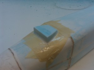
Initial scoop added to plug

Initial scoop added to plug

With the plug shape complete, the plug was spackeled and sanded several times to get it as smooth as possible.  The plug was then fiberglassed and sanded.  The fiberglass plug was then touched up with Bono before once again being sanded and then spray painted.  A final wet sanding of the painted surface completed the construction of the plug.
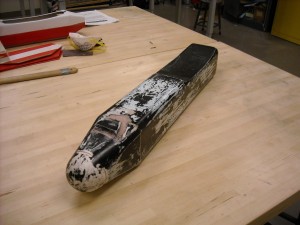
Completed fuselage plug

Completed fuselage plug

Return top