3D Laser Cutting With a 2D System

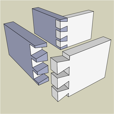
A typical laser cutter can make a precise 2D cut.  With rastering it is possible to etch the surface to add labeling.  However if the power of the laser can be finely controlled it is possible to make engineered depth cuts such as trenches or angled slopes.  This allows for laser cutting complex geometries such as a dovetail joint.

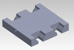
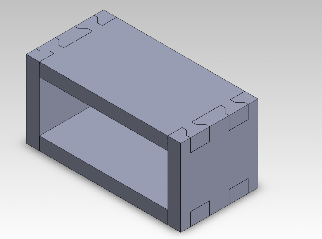
For this experiment a simple dovetail jointed box was modeled in Solidworks.

Although the long size of the box can be cut using typical methods, the end plates cannot.

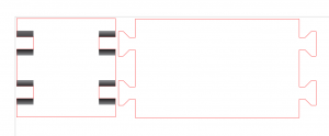
Both parts where placed into a solidworks drawing which was then exported to *.pdf.  This was then imported into Corel Draw 5.  The initial drawings appeared as shown below.

The lines to be cut were converted to “hairline” and RGB code <255,0,0>.  The Raster layer is defined by the gray-scale where back is 100% and white is 0%.  The power of the laser at 100% is set in the printer’s cut settings when the part is ready to be printed.  In this case, a gradient was drawn into the areas needing a depth cut.  The gradient allows for an angled cut between two particular depths.  The colors used and the number of passes to be completed were determined using a sort of look-up table.

Before this experiment, a set of colored squares were rastered into a material sample.  This was then repeated with two and three passses.  When selecting colors for the end plate cutting, the row that could reach the proper depth was selected.  In this case, the three-passes row was used with black at one end and a dark grey at the other.  This would result in a cut that was three black passes deep at one end and three dark-grey passes at the other.


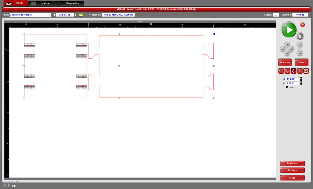
Shown in the laser cutting software below, the final design was then sent to the laser. For the first two passes, the vector cutting was set to be skipped.  This allowed the depth cutting to be finished before the laser cut out the final outline.

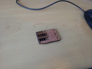
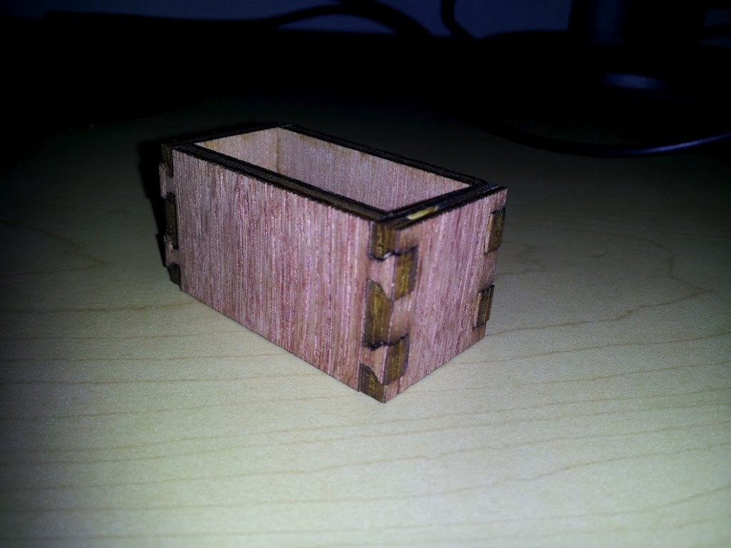
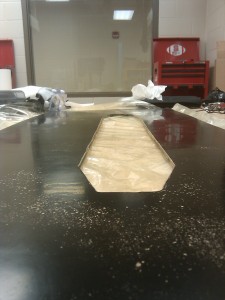
Finally the parts were removed from the laser cutter and the box shown below was assembled.  Two notable characteristics of the unglued box are its strength and its ease of assembly.  Even without glue the box doesn’t deform and tends to hold its shape.  Assembly was easier than just a tabbed box because once a joint was put together it had limited degrees of freedom about which to move.

Although this method can be time-consuming to setup, the final result creates good joints useful in engineered parts.
3D Printed Plug

In the process of manufacturing a senior design aircraft, a plug is used to create a negative mold on which aircraft fuselage skins can be laid up.  When the 2010-2011 senior design groups fabricated fuselage plugs, it was a lengthy process involving foam, plywood, fiberglass, epoxy, bondo, spackle, and an incredible amount of sanding.

This year a new method was tried with the intent of reducing the time required to manufacture the plug and allow for more complex geometric shapes to be used.  The availability of cheap rapid prototyping machines made this possible.  For this experiment the Ultimaker 3D printer in the Entrepreneurship Garage was used.  Based on previous experiments, PLA was used as the printed material.  North Carolina State University’s Aerospace Engineering Senior Design teams 3 and 4 participated in the experiment and provided the labor to integrate the printed parts into their aircraft plugs.

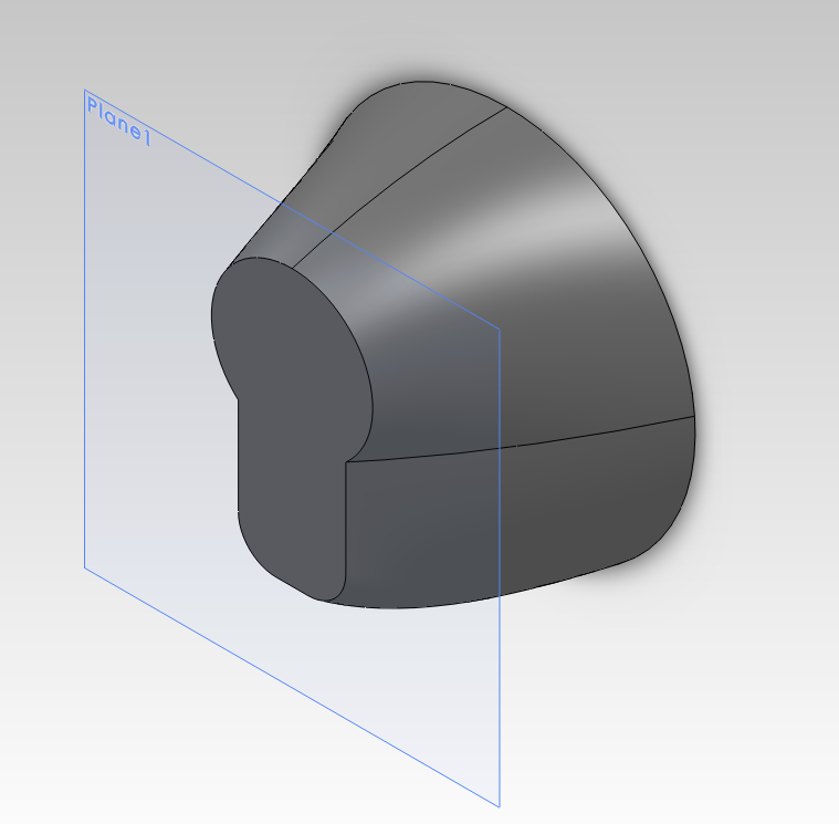
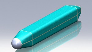
During the fall semester, the seniors designed the fuselage in solidworks.  The designs used a section of off-the-shelf PVC tubing as the main body with a nose cone and tail cone on either end to create the plug.  The nose and tail cones were modeled as separate parts and exported to *.STL format.

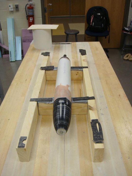
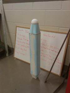
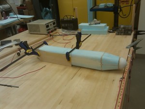
Team 3's Nose Cone

The UltireplicatorG software was then used to “slice” the model and create a GCODE instructions that the 3D printer could use.  In total, four parts were to be printed for the two teams.  Over the course of the printing a number of settings were experimented with.  The best results came when the solidworks models were simple solid objects with no shelling.  The slicer was then configured to print the object with zero infill and walls 3 layers thick.  This gave an object that was fast to print, but still rigid enough to be usable.  The final thickness of the wall was roughly 2-3 millimeters.

As this tail cone was being printed the extruder failed leaving several weak layers.

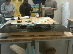
Once the printing was complete the seniors took over the process.  First an internal frame was cut to support, center, and join the cone to the PVC pipe.  The cone was then filled with plaster of paris to support the surface. Bondo and spackle were then applied to the surface to fill any cracks. Team 4 also added a shaft that stuck out the end of the mold.  This was then attached to a jury-rigged lathe.  The shaft was removed and sanded smooth once its purpose was served.

Rough sanded plug

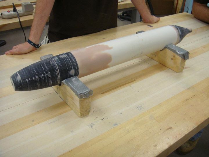
After hours of hard work the final plugs were completed.  The final sanded surface is so smooth that reflections are clearly seen on its surface.

Final plug

With the plugs complete the teams used wax and PVA to prepare the plug for the mold layup.  While team 4 did not have any trouble getting the plug out of the completed mold, team 3 did have some difficulties.  However, these difficulties have been attributed to the waxing and PVA processes and not the 3D printed PLA material.

Overall the experiment was successful in its goals of reducing time to create the plug and allowing for the creating of complex geometries.  In particular, sanding was reduced since only the final surface was sanded.  In the old process, sanding had to be done on the foam surface, fiberglass surface, and the painted surface all of which took time.  Additionally, the geometries would have been difficult to create by other methods. While team 4’s radially symmetric cones could have been created on a lathe, team3’s cones could not.  The success of this method should serve as a stepping stone for future designed using more complicated geometries.

Laser Cut Settings

Finding just the right settings for a laser cutter can be a time consuming guess and check process.  Additionally, using a calibration technique, such as the one detailed here, adds more time to the process of getting parts cut.  To ease this process here are the settings I use when cutting with a 60 watt Universal Laser Systems machine.

formica (add 0.003″ contour): Used to create smooth airfoil shapes.  The laser file does not store the z height settings.  You will need to turn on the z-axis and set a height of 0.025″.

Rapid Prototyping Nose Cones

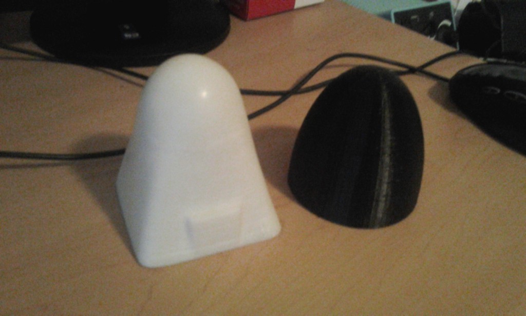
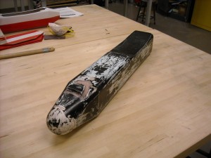
One of the compelling reasons for buying a Reprap Mondo was the potential for printing aircraft molds and parts.   Keeping with this goal, the Reprap Mondo was used to print the nose cone shown below in white ABS.  Its basic geometry is based on my senior design aircraft’s nose.  Recently I obtained access to an Ultimaker via the Entrepreneurship Initiative’s Garage.  Using the Ultimaker an elliptical nose cone was printed in black PLA.
Printed Nose Cones

Printed Nose Cones

The white nose cone pictured has been sanded and polished while the black cone is raw off the printer.  Overall the surface finish was similar between the two pieces.  Both did suffer from surface defects including an instance on both prints when their respective printers stopped extruding for a moment causing a large defect.  The white ABS cone did have the advantage that most of its defects were positive allowing them to be sanded while the black PLA cone has regular pit defects.  This is attributed to the ultimaker switching from the outer shell to the inner surface at such high speed.

Since the quality of the finished parts is rather close, the biggest difference between them is the time it took to print.  While the Mondo spent 6 hours printing the ABS piece, the Ultimaker only took 1.5 hours.  The comparison is not the best since the objects are distinctly different, but the conclusion stands that the Ultimaker is much much faster than the Mondo.

The difference in the materials is not particularly apparent in the final products.  Both parts are rigid, easy to sand, and fairly indestructible.  Since the parts are intended for use as molds, the strength to weight consideration is not present as it would be in flyable parts.  The important difference during this experiment was the ease of printing.  To prevent the ABS cone from warping it needed a heated bed, a heat gun, and super glue to ensure that it stayed on the platform.  The PLA cone needed none of this and printed just fine.
The one advantage that the Mondo has over the Ultimaker is its larger print volume.  However, the difficulties of printing in ABS have precluding actually using that greater volume.  Based on this, further work shall focus on the use of PLA as the material of choice.

Importing Airfoils into Solidworks

Solidworks is a great CAD program that can be useful in the design of aircraft.  However, one difficulty can be importing complex curves such as airfoils.  The challenge lies primarily in formatting the data such that solidworks can import it with its curves menu.  An example of properly formatted data is included below.

HS130

For data to be imported the file must contain X, Y, and Z coordinates in a tab-delimited file with no header.  Units may be included immediately after the number (“in” and “m” have been tested to work).  This can be accomplished with with an excel file by exporting the data as a tab-delimited file.  It may also be accomplished using the below python script to parse the data.  The script accepts arguements for filename (“-f” or “filename=”) and chord length in inches (“-c” or “chord=” ).  The airfoil data should be in a space-delimited file format.

foil2sldcrv

Once the data is ready to be loaded the process is fairly straight forward.

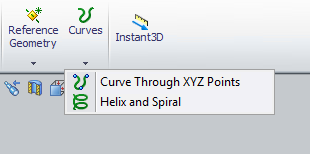
Solidworks Curves Menu

Solidworks Curves Menu

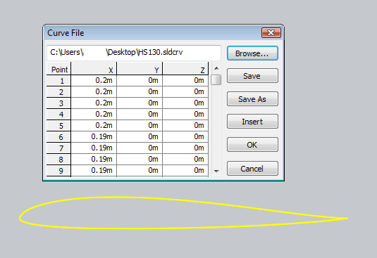
Clicking on the “Curve Through XZY Points” brings up a window from which the user may browse for a file containing their points.  This then allows the user to click “Browser” and select the file to import.

Curves menu with a sample airfoil loaded

Curves menu with a sample airfoil loaded

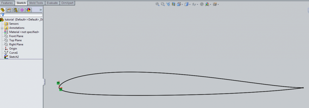
Once this has been completed a “Curve” object is added to the Feature Manager, typically found on the left side of the screen.  The user may then create a sketch incorporating the airfoil data by using “Convert Entities” and then selecting the airfoil curve using the Feature Manager.  It is also advisable to right-click the curve on the Feature Manager and select “hide” so as to avoid future confusion.

Imported airfoil data with Feature Manager at right

Imported airfoil data with Feature Manager at right

Deleting the the “On Edge” constraints (the small green squares shown in the above image) will allow the airfoil to be moved and scaled as desired.  This may create a second airfoil to appear that is attached at the same ending point.  Simply deleting the second outline seems to be the easiest way to fix the problem.  Once the sketch is free to move you can then constrain it as needed.

Constrained Airfoil

Constrained Airfoil

Laser Cutting Airfoils – Results

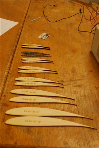
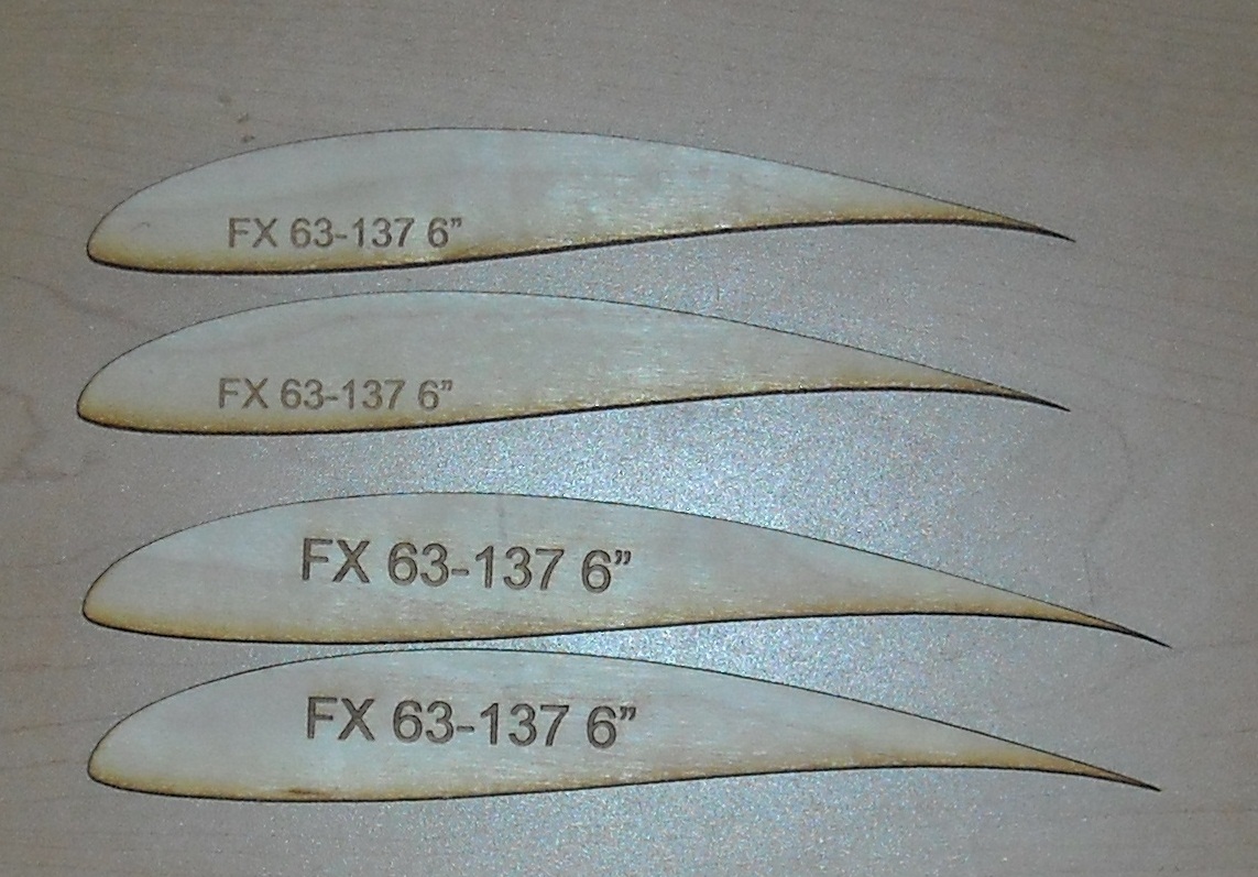
Using the previously detailed calibration method, a number of airfoil profiles were cut.

FX 63-137 Library

FX 63-137 Library

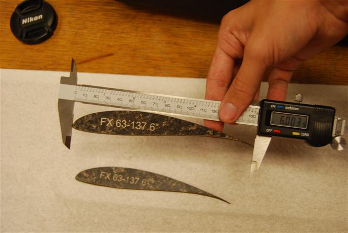
In cutting the airfoils, it was the thin trailing edge that was the greatest source of error due to the thickness of the laser’s cut.  As such, the chord length was used in assessing the accuracy of the airfoil profiles.  To determine the portability of the calibration technique, a 6″ chord airfoil was cut out of 1/8″ Birch Plywood, 1/4 Pine Plywood, and counter top material.  All three materials produced airfoils with an accuracy <0.005″.

FX 63-137 cut out of counter top material

FX 63-137 cut out of counter top material

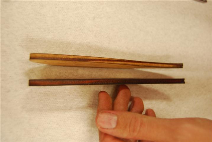
Before using the airfoils, there was some minor sanding required to clean the edges and holes for the pins that needed to be drilled out.  Using high grit sand paper for about a minute produced profiles that were ready for hot wire cutting.

sanding (Small)

1/4" Pine plywood before and after sanding

The 1/8″ birch 6″ FX 63-137 airfoil was used to make a test cut out of 60 PSI foam.  The cut was made difficult due to the lack of a positioning jig piece to go under it.  Despite this, the cut went smoothly and produced the below foam core.

cutFoam (Small)

Quick hot wire cut piece

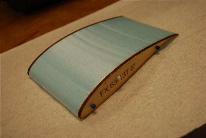
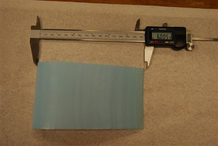
The final foam core was then removed from the profiles.  The surface finish was smoother than it looked.  The trailing edge has a slight bow to it since there were no support jigs to support the wire as it came off the profiles.  Despite this, when measuring the chord length of the core at the edges it was measured at 6.005″.

Final foam core

Final foam core

Laser Cutting Airfoils – Calibration

Power Setting Calibration

Having generated airfoil templates previously, the next step towards creating hot-wire templates was to get them cut.  Thanks to a generous sponsorship, this was accomplished by using Techshop RDU’s  Epilog Helix 24.   For these test pieces 3/8″ Birch Plywood was used.

airfoils

Test Airfoils

After a few test cuts the settings that would allow the piece to be cut after a single pass. were determined to be:

Vector: Speed 15%, Power 90%, Frequency 2000 hz

Additionally, each sample piece was labeled with the source file and dimensions by including a rasterized text.  The settings used were:

Raster:  Speed 25 % Power 80%

While the airfoils were an interesting piece to cut, the reader may clearly observe that in the above image the two six inch chord length airfoils are not the same size.  In fact, neither airfoil came out at six inches.  The smaller airfoil measured 5.8″ and the larger one measured 6.2″.

The cause of this is that while the laser’s cut is very fine, it does still have a thickness.  On the thin trailing edge of the airfoil this thickness results in a large effective change to the geometry.  To compensate for this, the cut line needs to be offset from the desired outline by a certain amount.  Determining this amount is the purpose of the calibration procedure below.

Offset Calibration

Once the settings that will be used for cutting the airfoil have been determined, the offset required may be calculated.  To do this start by cutting a rectangle.  The dimensions are arbitrary, so the actual size doesn’t matter.  During these tests, the setting used to cut the rectangle were etched into the side so they wouldn’t be lost.  After cutting, measure the width of the rectangle and the width of the rectangle’s cutout from the source material.  Subtracting these two measurements and then dividing by two then gives you the the offset to be used for that material.

The calibration can be applied to the laser template in Corel Draw during the below setup procedure.

  1. Open airfoil *.svg
  2. Move airfoil to desired (x,y) position, usually upper left corner
  3. Right-click and unlock airfoil pattern
  4. Click on line and then select all (ctrl-a)
  5. Select “Contour” option from menu
  6. Set contour size according to the calibration results
  7. Right-click and select “Break group apart”
  8. Select all the points on the new contour and set the line width to “hairline”, click apply afterwards
  9. Delete original airfoil
  10. Add label text, right-click and select “convert to curves”
  11. Print to Epilog Laser Cutter using correct settings under properties

Laser Cutting Airfoils – Templates

Using a hotwire technique to cut wings can make wing fabrication much faster and easier.  However, to do so requires that your airfoil go from being data points in a file to a physical guide.  Using a laser cutter to cut wood can make this process quicker and more accurate.  The first step, therefore, is to convert the airfoil data into a form that can be used by the laser cutter.

Sample Airfoil

Sample Airfoil

Airfoil data is nominally stored as a set of coordinates in a space delimited CSV file.  The laser cutter uses vector and raster files to control the laser.  Thus, to control the laser the airfoil coordinates simply need to be converted into a poly-line in an SVG image file.  An SVG file is actually just an XML file and, conveniently, there is a python library for creating these files.

The below code loads, formats, and then creates the polyline.

    scale = 96
    xOffset = 0.5
    yOffset = 2

    pts = ""
    line= 0
    # Read airfoil data
    spamReader = csv.reader(open(filename, 'rb'), delimiter=' ', quotechar='|', skipinitialspace="true")
    for row in spamReader:
        #Skip the first line of header information
        if(line!=0):
            #Format and store in a string
            pts+= str((float(row[0])*chord+xOffset)*scale)+","+str((float(row[1])*-chord+yOffset)*scale)+"  "
        line=1            

    oh=ShapeBuilder()
    mySVG=svg("test")
    #Create a polyline using the formatted airfoil data string
    pl=oh.createPolyline(points=pts,strokewidth=0, stroke='blue')
    mySVG.addElement(pl)

The addition of some code to handle arguments for the airfoil’s filename and chord length and saving the data then finishes the code.  The next step will be to test the pattern on a laser cutter later this week.  The “scale” parameter is determined by Corel Draw which imports svg files at 92 pixels per inch.  The current code is included below.  This version requires the svg module at pySVG.

foil2svg

Sample Files:

FX 63-137 Airfoil

FX 63-137 Template

The program can easily be controlled from the command line using a statement formatted as below.  Where the chord length is defined in inches by the “-c” flag and the airfoil file location by the “-f” flag.  The program will save the output in the same directory and with the same filename as the airfoil except with a *.svg extension.

python foil2svg1.py -c 3 -f ./fx63137sm.dat

*** NOTE pySVG recently updated and is no longer compatible with this program.  A revised version will be available shortly (7/21/2011)

Parting Plane Fabrication

Once the fuselage plug has been completed it may now be used as the basis for the fabrication of the fuselage molds.  This process starts with the fabrication of a parting plane.  The parting plane, as its name implies, is used to form the plane between the two halves of the fiberglass mold.  It will only be used for creating the first half of the mold.  The second half will be laid up against the first half.

To create the parting plane a rough cut slightly smaller than the body is made with a miter saw into a plywood piece.  This is then carefully sanded down so that the fuselage plug just fits.

parting_plane

Rough parting plane being sanded

Once the hole is finished, the entire board is sanded, painted, sanded again, and then waxed.  Once this is complete, the parting plane should have an almost mirror-like finish to it.

parting_plane

Mirror finish on completed parting plane

To support the parting plane and hold the plug halfway through the hole, a sub-structure is created under the parting plane.  It is important to ensure that holes drilled will be beyond the area over which fiberglass will be laid for the mold.

parting_plane_substructure

Parting plane with sub-structure and plug

Fuselage Plug Fabrication

Since the beginning of the semester we have made significant strides forward in building our senior design aircraft.  This post will focus on the fabrication of the fuselage plug.  The goal is to produce the fuselage geometry such that it may be used to create molds from which the actual aircraft skins may then be manufactured.

Render of the base plug to be created.

Render of the base plug to be created.

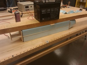
The core of the plug was made using a combination of foam and thin plywood.  As shown below, the plywood bulkhead serve to create the profile shape of the body while the lengthwise pieces of plywood serve to keep the bulkheads positioned and aligned correctly.  Foam blocks where then glued into the spaces and cut using a hot wire bow and a steady hand.  Once cut, the bulkheads are shimmed as needed and the gaps filled with epoxy.

Early stage of plug fabrication

Early stage of plug fabrication

To create the spherical nose of the aircraft, a foam ball from a crafts store was shaved down on a sanding belt until the correct circumference was had.  This was then epoxied to the front bulkhead.  Once all the foam was in place, the remaining seams and imperfections were covered in spackle and sanded down.

Plug covered in spackel ready for sanding

Plug covered in spackel ready for sanding

Next, the wing saddle is cut out of the plug.  This wing will sit such that the leading edge and trailing edge will sit flush with the body.  The cut is accomplished by clamping a plywood profile of the bottom of the wing to the plug.  Clamps, screws, and a plywood offset piece all work to keep the profile in place.  Again the cut is completed with a hot wire bow and a steady hand.

wing_saddle_cut

Plug ready for wing saddle to be cut

The last remaining feature to be added was the ventilation scope.  The basic shaped was cut out of foam using a template and the hot wire bow.  This was then glue to the plug.  A mix of Capasil and epoxy were then applied along the edge and smoothed with a gloved finger to create a bevel.  After curing, Bondo was used to create a smooth transition from the rear of the scoop to the body.

Initial scoop added to plug

Initial scoop added to plug

With the plug shape complete, the plug was spackeled and sanded several times to get it as smooth as possible.  The plug was then fiberglassed and sanded.  The fiberglass plug was then touched up with Bono before once again being sanded and then spray painted.  A final wet sanding of the painted surface completed the construction of the plug.

Completed fuselage plug

Completed fuselage plug

Return top