3D Printed Plug

In the process of manufacturing a senior design aircraft, a plug is used to create a negative mold on which aircraft fuselage skins can be laid up.  When the 2010-2011 senior design groups fabricated fuselage plugs, it was a lengthy process involving foam, plywood, fiberglass, epoxy, bondo, spackle, and an incredible amount of sanding.

This year a new method was tried with the intent of reducing the time required to manufacture the plug and allow for more complex geometric shapes to be used.  The availability of cheap rapid prototyping machines made this possible.  For this experiment the Ultimaker 3D printer in the Entrepreneurship Garage was used.  Based on previous experiments, PLA was used as the printed material.  North Carolina State University’s Aerospace Engineering Senior Design teams 3 and 4 participated in the experiment and provided the labor to integrate the printed parts into their aircraft plugs.

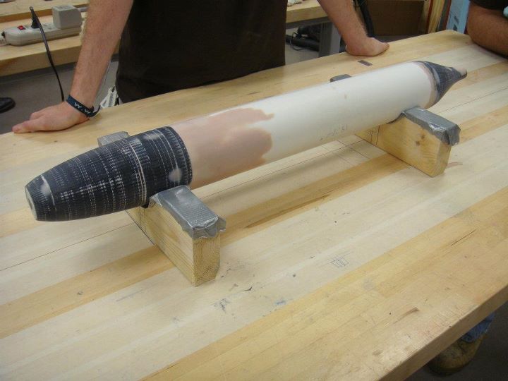
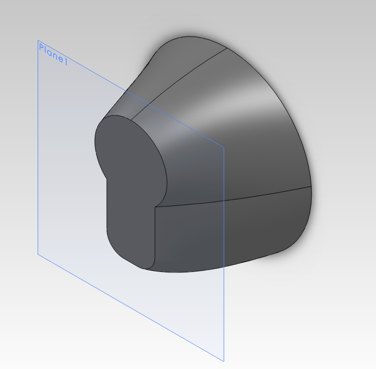
During the fall semester, the seniors designed the fuselage in solidworks.  The designs used a section of off-the-shelf PVC tubing as the main body with a nose cone and tail cone on either end to create the plug.  The nose and tail cones were modeled as separate parts and exported to *.STL format.

Team 3's Nose Cone

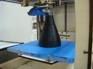
The UltireplicatorG software was then used to “slice” the model and create a GCODE instructions that the 3D printer could use.  In total, four parts were to be printed for the two teams.  Over the course of the printing a number of settings were experimented with.  The best results came when the solidworks models were simple solid objects with no shelling.  The slicer was then configured to print the object with zero infill and walls 3 layers thick.  This gave an object that was fast to print, but still rigid enough to be usable.  The final thickness of the wall was roughly 2-3 millimeters.

As this tail cone was being printed the extruder failed leaving several weak layers.

Once the printing was complete the seniors took over the process.  First an internal frame was cut to support, center, and join the cone to the PVC pipe.  The cone was then filled with plaster of paris to support the surface. Bondo and spackle were then applied to the surface to fill any cracks. Team 4 also added a shaft that stuck out the end of the mold.  This was then attached to a jury-rigged lathe.  The shaft was removed and sanded smooth once its purpose was served.

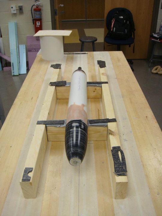
Rough sanded plug

After hours of hard work the final plugs were completed.  The final sanded surface is so smooth that reflections are clearly seen on its surface.

Final plug

With the plugs complete the teams used wax and PVA to prepare the plug for the mold layup.  While team 4 did not have any trouble getting the plug out of the completed mold, team 3 did have some difficulties.  However, these difficulties have been attributed to the waxing and PVA processes and not the 3D printed PLA material.

Overall the experiment was successful in its goals of reducing time to create the plug and allowing for the creating of complex geometries.  In particular, sanding was reduced since only the final surface was sanded.  In the old process, sanding had to be done on the foam surface, fiberglass surface, and the painted surface all of which took time.  Additionally, the geometries would have been difficult to create by other methods. While team 4’s radially symmetric cones could have been created on a lathe, team3’s cones could not.  The success of this method should serve as a stepping stone for future designed using more complicated geometries.
RepRap Mondo – Part 8 – Belts

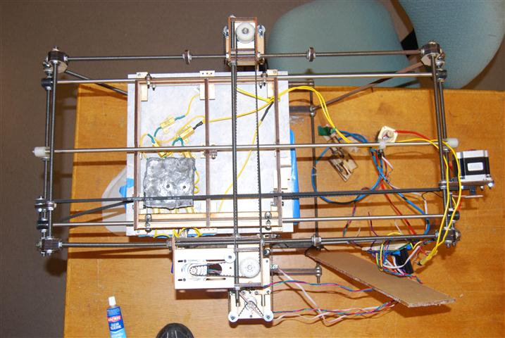
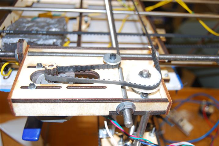
The RepRap Mondo has three belts that need to be installed.  An overview of the belts as seen from the bottom of the machine is shown below.  The large lead block under the bed is just pinning down the resistors while the adhesive cures and is not apart of the machine.

Bottom view of the machine

Bottom view of the machine

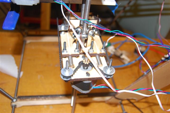
The belt slips over the idlers and motors previously installed on the Y-Axis.  The belt ends are then clamped to the head mount under light tension.

Elevator Belts

Elevator Belts

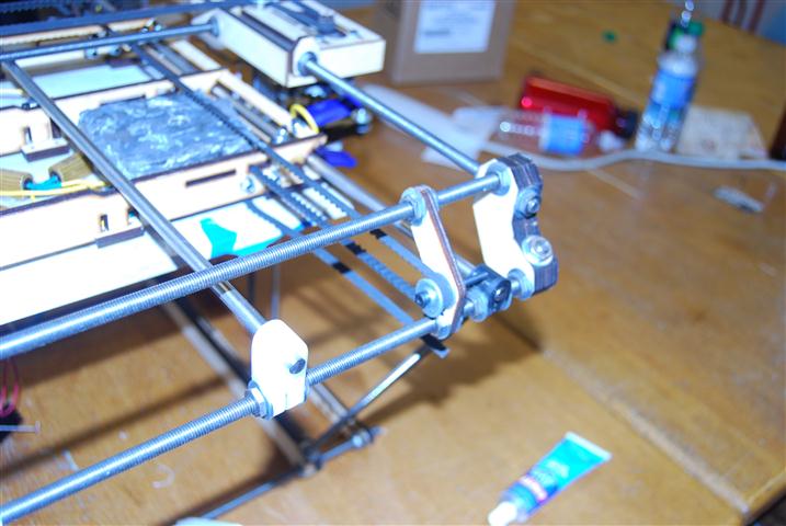
The Z-axis belt is a continuous loop and is installed under light tension.  The belts should not rub against any other structures.  The idler wheel shown below is built similarly to those on the elevator.
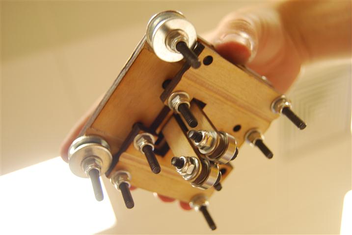
Z-axis belts

Z-axis belts

The X-axis idler simply mounts to the opposite end of the machine to the X-axis motor.  The ends of the belt are clamped to the bottom of the bed.

X-axis idler

X-axis idler

RepRap Mondo – Part 7 – Endstops

The RepRap Mondo’s mechanics are one of its strongest attributes, however in designing the machine it appears that the endstops were completely forgotten.  As a result of this and a complete lack of instructions, the locations and mounts for all the endstops shown are based only on our conjecture, but having run our machine for a while now we can confirm that these positions do work.

The cables that came with the endstops do not fit properly on the pins from the endstop.  As a result, they have a tendency to pop off.  We cut off the ends an soldered them directly to the contacts inside the end-stops.  These were exposed by cutting part of the end-stop enclosure off.
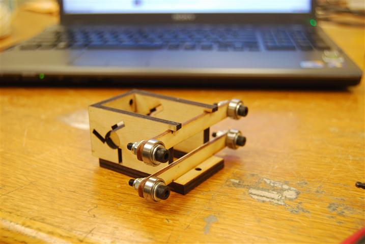
X end-stop

X end-stop

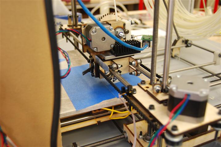
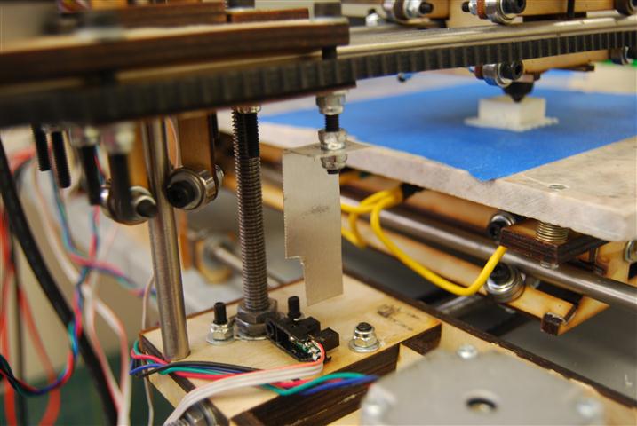
The X-axis end-stop sensor was mounted to an extra hole we conveniently found on the elevator assembly.  The kit ships with a piece of thin aluminum that we cut down to the size shown.  The belt clamp was loosened and the aluminum plate was slipped in.  On tightened down the clamp held the aluminum quite well.  There is a small angle cut into the bottom of the aluminum plate so that if it gets bumped down the angle will cause the piece to get pushed back up instead of being mangled.

Y End-stop

Y End-stop

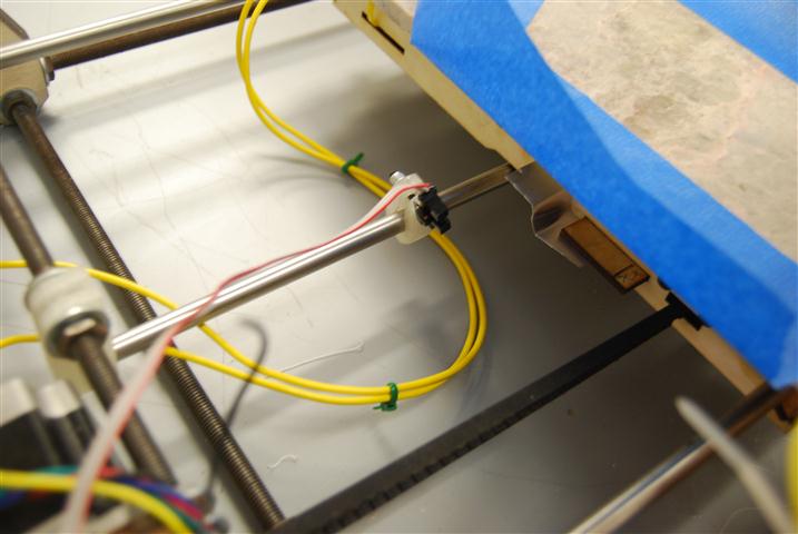
The Y end-stop sensor mounts to a small RepRapped piece which slides over the Y axis smooth rods.  A bolt clamps the rod and holds the sensor.  A small piece of wood was glued to the bed to make a small shelf to mount the aluminum piece.  The Z-bend in the aluminum makes it easier to adjust.  The aluminum is super-glued to the bed frame shelf.  To clear the deck, the sensor is bent back at a slight angle.   It would probably also work to mount the sensor rotated 180 to avoid needing to tilt it.

The Y end-stop sensor is mounted so far forward in the above picture because our marble bed is currently 6 inches shorter than the warped 18″ bed that the kit shipped with.

Z End-stop

Z End-stop

To mount the Z End-stop we glued the sensor on its side to the base of the elevator.  We then cut a hole in the aluminum piece and used lock-nuts to attach it to the bottom of one of the screws used int he elevator assembly.  This is the only end-stop mount that is finely adjustable and is so specifically because you will need to tune this axis the most.  Slight adjustments can make a big difference.

RepRap Mondo – Part 6 – The Bed

Aluminum Bed

The Mondo ships from Techzone with an aluminum bed.  The 18″ x 12″ bed comes with six holes for mounting to the base support.  Although the holes are nicely chamfered they did not include machine screws to go with the holes.  None of the screws that fit through the holes were flush with the bed either.  After hitting one of the bolt heads with the extruder nozzle we made a run to the hardware store to get a pack of 4-40 1″ screws with nuts.
Techzonecom warped metal bed

Techzonecom warped metal bed

With the proper screws in place we then set about leveling the bed.  Several hours later I discovered that the bed was badly warped such that no amount of tweaking would make it flat.  We measured a tip deflection of 3-4 mm near the ends which was a significant problem given that the layer thickness was 0.4 mm.  For a while we continued printing by restricting the build area to a three inch square near a corner we leveled relative to the head.

Glass Bed

This deficiency in the bed lead us to our first alternate bed made from 3mm glass, which turned out to be 2.3 mm when meaured with calipers.  The 18″ x 12″ glass bed was cut for us and only cost $5.  It was mounted on top of the aluminum bed by placing six blobs of “clear silicone, waterproof sealant” that we picked up from the hardware store.  We selected it based on its tolerance of heat up to 175 degrees Celsius which was above any of the temperatures we expected the bed to see.  Once the glass was set on the silicone we then shimmed and squished down the bed as needed to get it level.
Remains of the glass bed

Remains of the glass bed

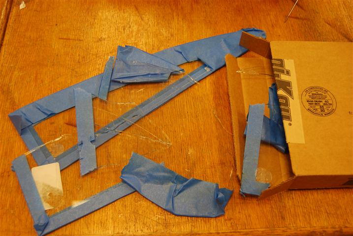
However, during later prints we found that heating the bed with a heat gun resulted in superior print quality with reduced warping.  Unlike the metal bed which nicely conducted the heat through out, the glass bed required that heat be applied locally at the printing area.  Although this arrangement worked for a while, as we tried to increase the local temperature the local heating eventually caused a crack to form across the bed starting from a chip on the edge.  The glass bed wasn’t destroyed at that point, but rather as we tried to get the glass bed off we had to resort to breaking the bed down into more manageable, albeit razor sharp, sections.

Marble Bed

It was at this point that the suggestion was made that we try a thin ceramic material used as a base material in thick film circuit deposition.  It was quickly determined that there was no local supplier and the material would be expensive.  However, 3/8″ granite and marble floor tiles are cheaply available at the local hardware store and come in 12″ and 18″ squares.  For this first experiment we purchased a 12″ marble tile for $2.28.
Marble bed installed

Marble bed installed

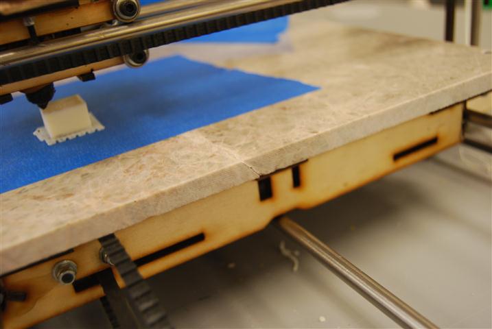
The marble bed has proven over the last week to be incredibly flat, durable, and gorgeous.  Mounting to the bed support was accomplished by drilling four holes with a tile bit set before then chamfering the holes with a larger bit.  It is also noteworthy that although this bed takes a while to heat up, once it is hot it tends to stay hot for an extended period of time.
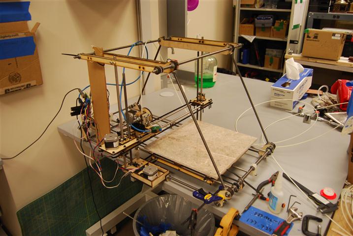
The only problem he have had is in our selection of an individual tile. The tile that we selected had a natural crack running through it that was visible on both the top and bottom of the tile.  The crack is more obvious when the bed is heated up.  Despite this, once a printing surface is laid down, such as the painter’s tape shown, the crack has no effect on the usability of the surface.
A natural crack in the marble

A natural crack in the marble

RepRap Mondo – Part 5 – Stepper Motor

The RepRap Mondo requires 4 motors for the three axes of motion and the extruder.  Three of these motors have four wires, but the Y-axis motor is larger and has six wires.  Techzonecom cut the white and yellow wires short presumably so that the person using this motor would not make the mistake of using them.  However, as we soon demonstrated, there is no color coding associated with stepper motors.

When we wired up the Y-axis motor using the same color pattern as the smaller motors we observed very unusual behavior.  The bed moved smoothly in the positive direction, but when commanded to go in the negative direction the bed shook violently and continued to move in the positive direction.  Using an Ohm meter Michael Yenik, my partner on this project, determined that the blue wire was in fact a center tap on the motor instead of being the end of the coil.  After soldering an extension on to the yellow wire, which was connected to the end of the coil, and connecting it in place of the blue wire we were able to get the bed to smoothly move in both directions.

Stepper motor with needed wire cut short

Stepper motor with needed wire cut short

RepRap Mondo – Part 4 – Extruder

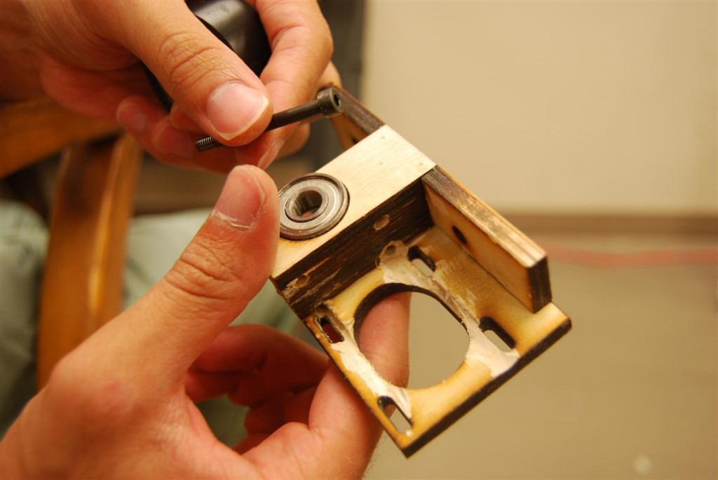
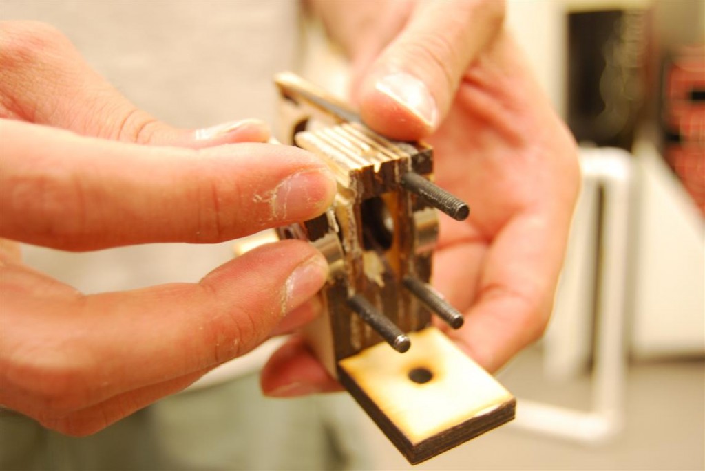
The extruder seemed like it would be an easy component to assemble thanks to good instructions on the reprap site.  However, it quickly became evident that techzone’s laser cut version was going to be a much greater challenge.   The first issue that arose was that the screws closest to the motor mount could not be inserted into the holes until we routed the channels as shown in the below image.

Wade's Extruder with minor alterations

Wade's Extruder with minor alterations

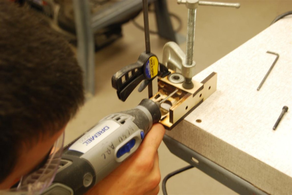
Further modifications were required because the screw heads could did not clear the motor.  To fix this, extra material was routed out to make room for them.  The challenge of this is quite evident below.

Modifications in progress

Modifications in progress

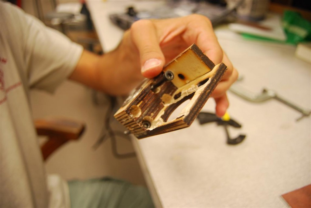
These holes would also need to be made deeper to allow the screws to stick out far enough for springs and nuts to be added on the other side.

Modifications complete

Modifications complete

Bolts sticking out the appropriate distance

Bolts sticking out the appropriate distance

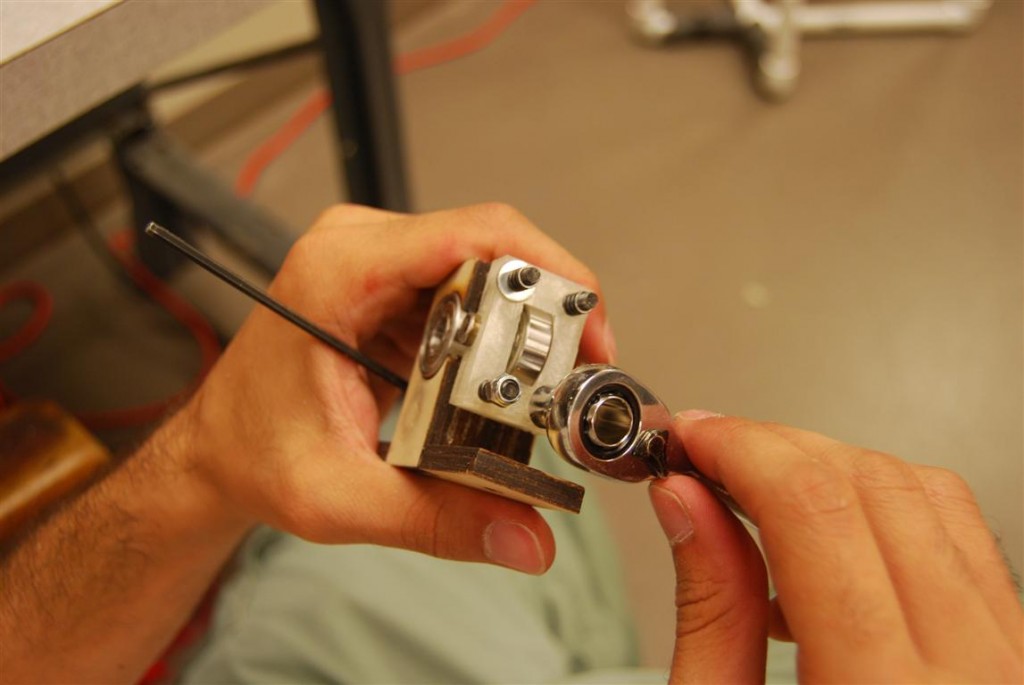
After much modification, we were finally able to get the assembly put together.  Between the two top pictures you can see that the screw holes for mounting the extruder to the reprap are covered by the motor and spring assembly making it impossible to swap the extruder without a complete disassembly of the device.

Assembly of the feeder

Assembly of the feeder

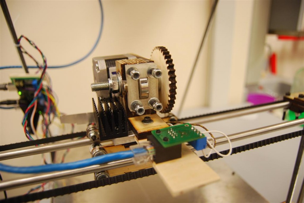
The motor, gears, and extruder drive shaft were then assembled.  One thing we learned later during tuning is that washers need to be added to the extruder drive shaft such that the gripping surface is aligned with the filament.

Extruder finished and mounted

Extruder finished and mounted

The tuning process was mostly concerned with the tension of the four springs.  The problem was that the springs can only be adjusted with the motor removed.  This necessitated the removal of the drive shaft as well because the large gear blocks access to the motor’s mounting screws.

RepRap Mondo – Part 3 – Frame

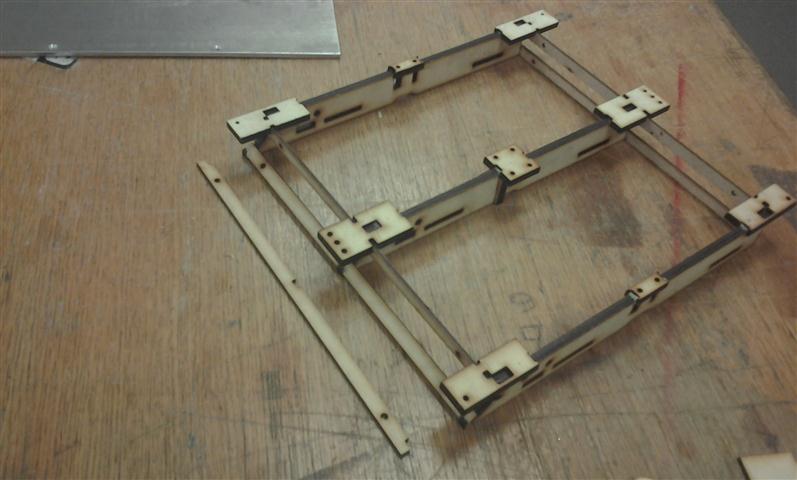
Without instructions, our first task was to identify which rods went where.  Once fitted together it becomes clear where the rods go.

Frame roughly assembled

Frame roughly assembled

The base mounts for the elevator assembly was then slid on to the long base rod.  Wooden feet were then added as well as washers, and nuts to keep them all in place.

Elevator base slid on to base threaded rod

Elevator base slid on to base threaded rod

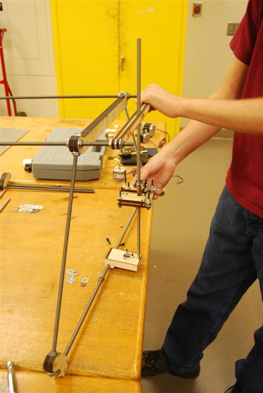
After loosely adding washers and nuts to keep the frame from falling apart, the smooth rod for the elevator assembly was slipped between the two outer pieces of wood.  The base of the rod was then set into the base and the nuts at the top of the structure were adjusted to keep the rod straight vertical.

Elevator assembly rod connected to top of frame

Elevator assembly rod connected to top of frame

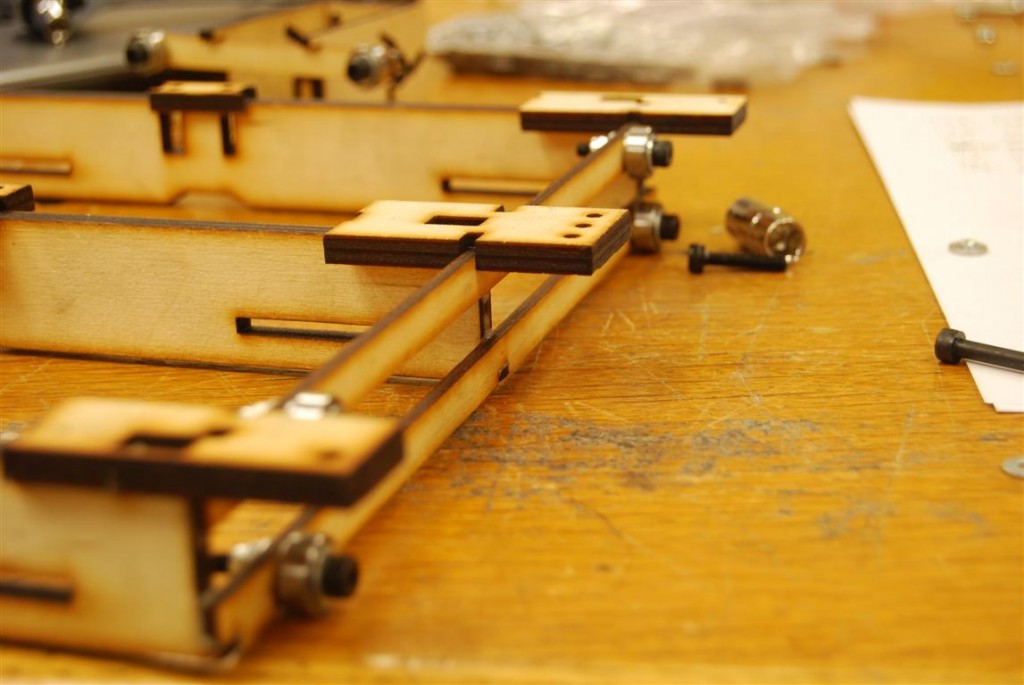
The bed was then prepared by adding roller assemblies to it.  These are similar to those used on the elevator assembly.  On the side shown there are three pairs of two rollers.  On the opposite side there are three pairs of three rollers.  In the middle is a single roller which will sit on top of the center smooth rod.

DSC_0332 (Medium)

Assembling rollers onto bed support

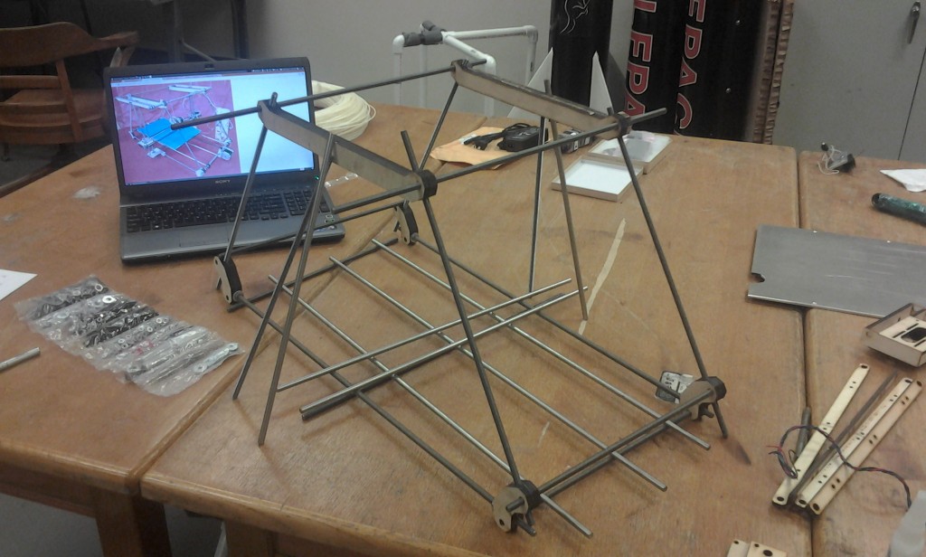
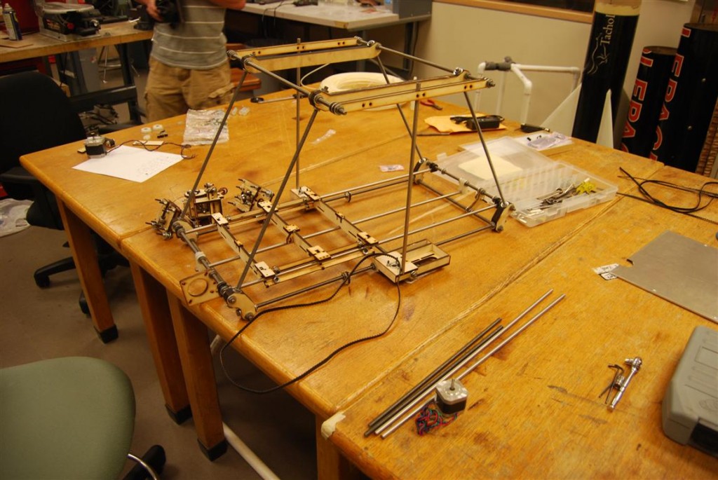
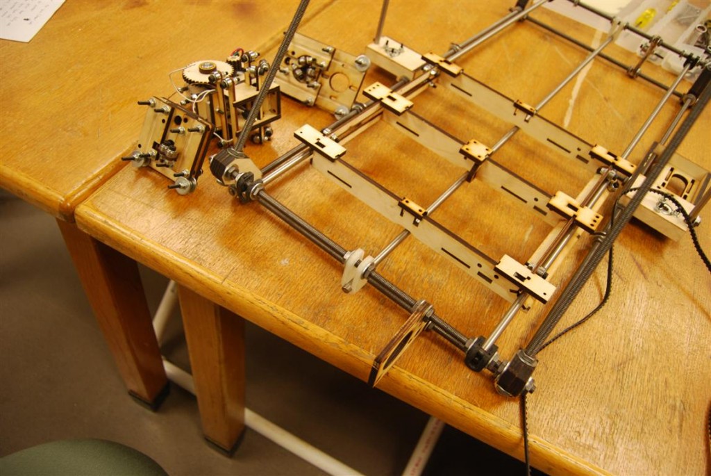
The rods for the bottom of the frame were then slipped together.  The goal being to produce the overall assembly shown below.

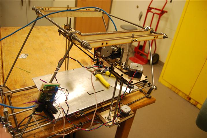
High level view

High level view

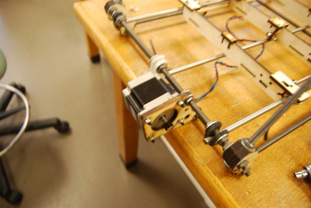
On the motor’s end of the frame, two black rod supports were added on either end.  A longer white support was put in the middle and the motor mount to its right.

Close up of Y-axis motor

Close up of Y-axis motor

On the other side is a similar assembly, but with a roller bracket support in place of the motor.

Bed support

Bed support

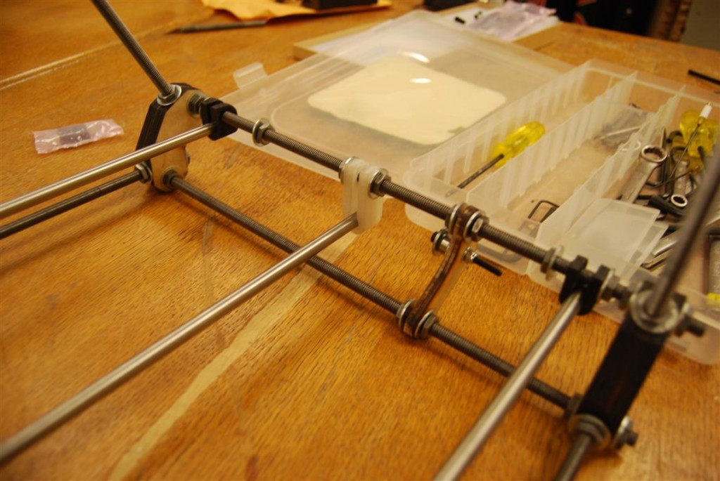
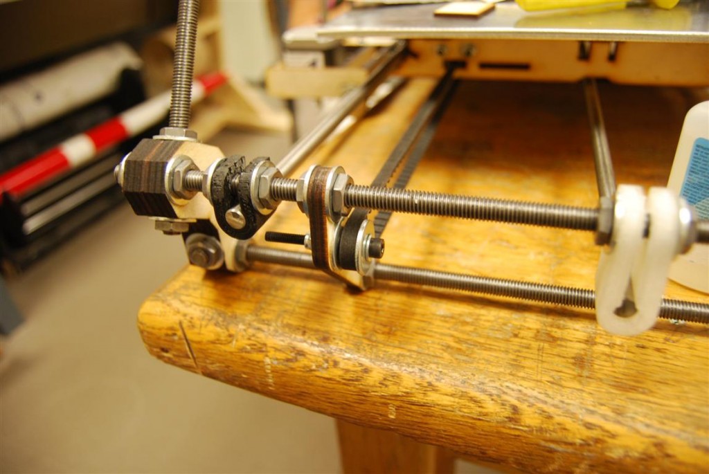
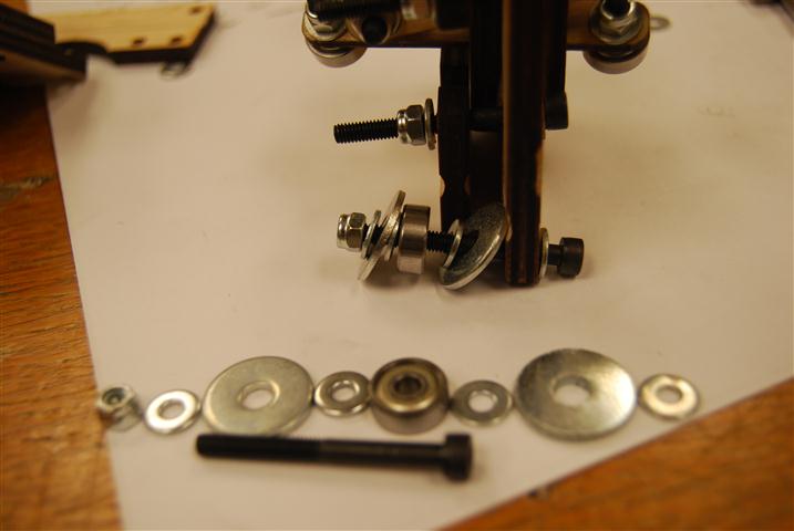
Closer up you can see the multitude of nuts and washers needed to keep everything in its place.  You can also see how the belt will be positioned later on.

Bed support bracket close-up

Bed support bracket close-up

Once everything was loose fitted, the rod with three rollers on it was slid out and the bed installed.  Once the outer frame was squared and leveled, the rod with three rollers was aligned a specific distance from the outer bracket.  The other rod supports were then shifted as needed so that they ran straight under their respective rollers.

Bed positioned for alignment

Bed positioned for alignment

RepRap Mondo – Part 2 – Elevator Assembly

Roller Assembly

Roller Assembly

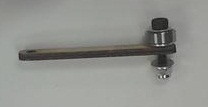
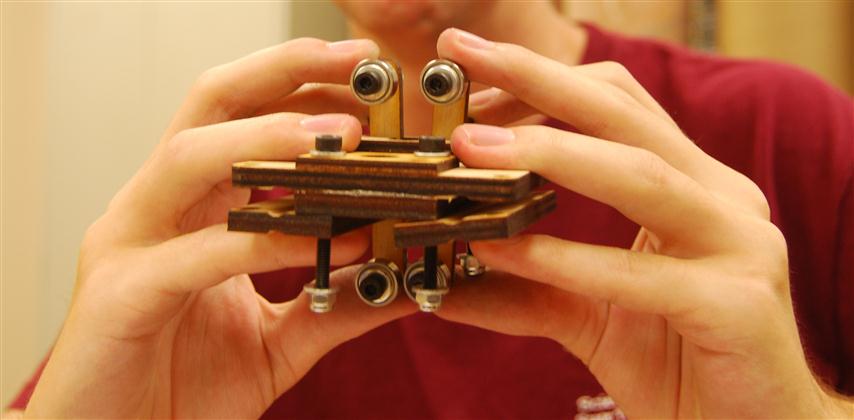
The kit includes (5) short roller mounts and (3) long roller mounts.  As pictured below, a roller assembly is bolted into each of the two holes.  The first roller assembly can be attached with the mount free of the larger assembly.  The second should be attached after being inserted.  Once attached the bolt and lock nut can be screwed down snug.

Roller Assembled

Roller Assembled

Lift Bolt

Lift Bolt

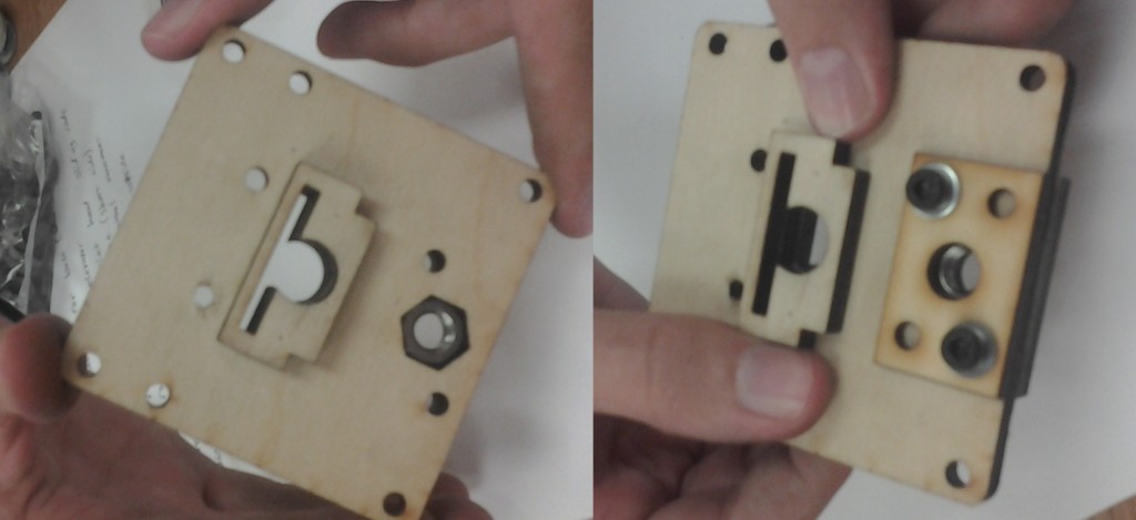
The plate also has a hexagonal cutout for a large nut.  After inserting the nut, the retainer plate can be placed over it.

Elevator Left Assembly

Elevator Left Assembly

Next, the two grooved rectangular plates with the square cutout are added onto the bottom of the long bolt holding the retainer plate on.  Leave these bolts loose for the time being.

DSC_0305 (Small)

Belt Roller Assembly

On each of the outer corners not covered by the last step, a belt roller assembly is added as shown above.

Complete Left Elevator

Complete Left Elevator

The final piece should look similar to the above (One bolt is missing).   The assembly for the right side of the elevator is very similar.  There is just one more set of rollers and the plates with the circular cutout are used instead.

Extruder Mount

Extruder Mount

The extruder mount uses the three long roller mounts.  In addition, two roller mounts are already attached to the device and also get rollers.

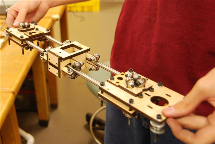
Elevator Assembly

Elevator Assembly

Finally, the two shorter smooth rods are inserted into the assembly.  Keep the bolts loose enough that the rod length can be adjusted as needed later in the setup.

RepRap Mondo – Part 1 – Unboxing

In May of 2011, http://techzonecom.com LLC introduced the RepRap Mondo.  With a print volume of 18″x12″x11″ it is a big printer.  We decided to purchase the Mondo after getting timely feedback to questions asked of the company.  After a slight delay the printer kit arrived.  What follows will hopefully serve as a guide to others building a Mondo and as a close-up tour of this fascinating machine.

Unboxing

The first surprise was that, as of this time, there are no instructions for how to assemble the Mondo.  The website simply says that its construction is similar to that of the Mendel or Huxley.  However, no one on the team has assembled either of those machines before, and the instructions on the RepRap site were not helpful.  To assemble the Mondo, the pictures of the prototype as posted on the TechZoneCom website were used as our guide.

It is important to note here that because we never had official instructions we cannot be sure that we did everything as it was intended.  All we can claim is that at the end of the project we have a working device.  When official instructions are released, we will edit these posts to note where our version differs.

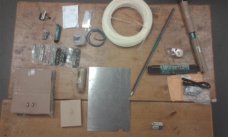
All the parts as taken out of the box

All the parts as taken out of the box

After unboxing the parts, we divided them into a few categories: rods, large frame pieces, small pieces, hardware, and electronics.  Almost everything needed to get the Mondo printing is included except for the printing material and the computer and USB cable to drive it.  We ordered a five pound roll of ABS to go with ours.

Major parts arranged by eventual positions

Major parts arranged by eventual positions

To get a sense of what things were we started by arranging the parts roughly be where they belonged according to the pictures.

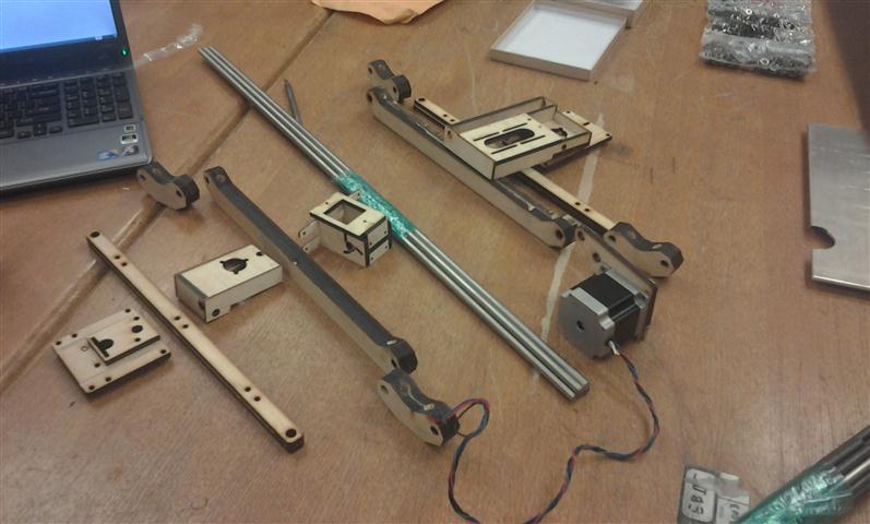
Small Parts

Small Parts

The small parts were grouped to keep track of how many we had. Note that the two plates on the bottom left with five holes are stacked two high.  We later discovered that there should have been two of the small piece rectangle with two holes as shown on the top row.  Luckily we were able to fabricate a replacement easily.

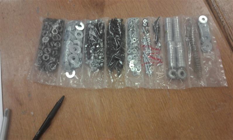
Hardware

Hardware

Various pieces of hardware used to assemble the device are included in the shown sub-divided plastic bag.  We simply cut one end off to keep the parts organized and accessible.  Some of the parts are mixed together which became frustrating at times.  There are a lot of locking nuts.  Before starting assembly make sure that you have a ratchet set for  the lock nuts.  This will make the assembly go much faster.

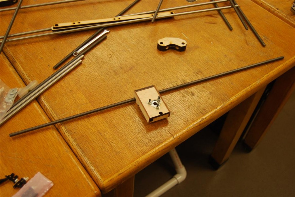
Bed support with loose part

Bed support with loose part

A number of the laser cut parts assemblies came pre-glued.  This, without a doubt, saved us many hours of gluing and frustration.  One example is the bed support shown above.  One piece did fall off sometime during transportation, but it was easily re-attached.

Return top