RepRap Mondo – Part 5 – Stepper Motor

The RepRap Mondo requires 4 motors for the three axes of motion and the extruder.  Three of these motors have four wires, but the Y-axis motor is larger and has six wires.  Techzonecom cut the white and yellow wires short presumably so that the person using this motor would not make the mistake of using them.  However, as we soon demonstrated, there is no color coding associated with stepper motors.

When we wired up the Y-axis motor using the same color pattern as the smaller motors we observed very unusual behavior.  The bed moved smoothly in the positive direction, but when commanded to go in the negative direction the bed shook violently and continued to move in the positive direction.  Using an Ohm meter Michael Yenik, my partner on this project, determined that the blue wire was in fact a center tap on the motor instead of being the end of the coil.  After soldering an extension on to the yellow wire, which was connected to the end of the coil, and connecting it in place of the blue wire we were able to get the bed to smoothly move in both directions.

Stepper motor with needed wire cut short

Stepper motor with needed wire cut short

Importing Airfoils into Solidworks

Solidworks is a great CAD program that can be useful in the design of aircraft.  However, one difficulty can be importing complex curves such as airfoils.  The challenge lies primarily in formatting the data such that solidworks can import it with its curves menu.  An example of properly formatted data is included below.

HS130

For data to be imported the file must contain X, Y, and Z coordinates in a tab-delimited file with no header.  Units may be included immediately after the number (“in” and “m” have been tested to work).  This can be accomplished with with an excel file by exporting the data as a tab-delimited file.  It may also be accomplished using the below python script to parse the data.  The script accepts arguements for filename (“-f” or “filename=”) and chord length in inches (“-c” or “chord=” ).  The airfoil data should be in a space-delimited file format.

foil2sldcrv

Once the data is ready to be loaded the process is fairly straight forward.

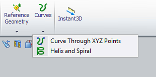
Solidworks Curves Menu

Solidworks Curves Menu

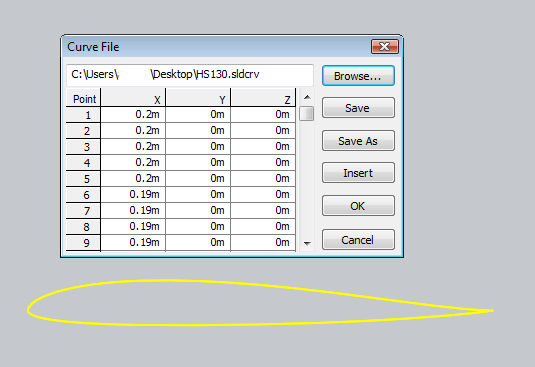
Clicking on the “Curve Through XZY Points” brings up a window from which the user may browse for a file containing their points.  This then allows the user to click “Browser” and select the file to import.

Curves menu with a sample airfoil loaded

Curves menu with a sample airfoil loaded

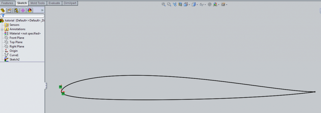
Once this has been completed a “Curve” object is added to the Feature Manager, typically found on the left side of the screen.  The user may then create a sketch incorporating the airfoil data by using “Convert Entities” and then selecting the airfoil curve using the Feature Manager.  It is also advisable to right-click the curve on the Feature Manager and select “hide” so as to avoid future confusion.

Imported airfoil data with Feature Manager at right

Imported airfoil data with Feature Manager at right

Deleting the the “On Edge” constraints (the small green squares shown in the above image) will allow the airfoil to be moved and scaled as desired.  This may create a second airfoil to appear that is attached at the same ending point.  Simply deleting the second outline seems to be the easiest way to fix the problem.  Once the sketch is free to move you can then constrain it as needed.

Constrained Airfoil

Constrained Airfoil

RepRap Mondo – Part 4 – Extruder

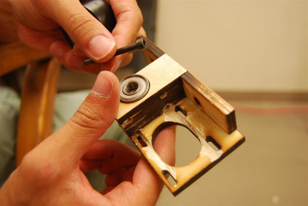
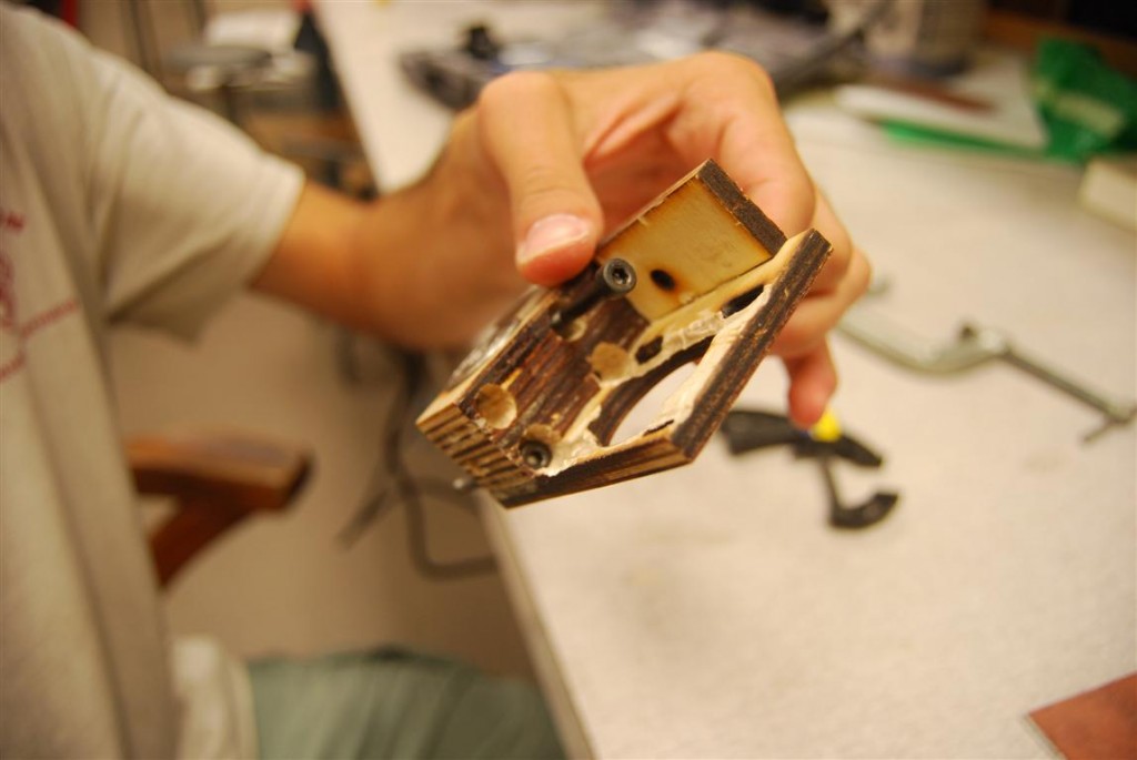
The extruder seemed like it would be an easy component to assemble thanks to good instructions on the reprap site.  However, it quickly became evident that techzone’s laser cut version was going to be a much greater challenge.   The first issue that arose was that the screws closest to the motor mount could not be inserted into the holes until we routed the channels as shown in the below image.

Wade's Extruder with minor alterations

Wade's Extruder with minor alterations

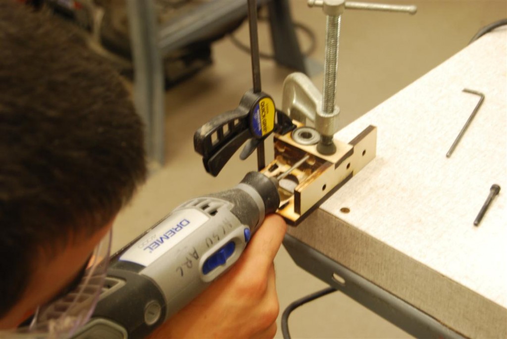
Further modifications were required because the screw heads could did not clear the motor.  To fix this, extra material was routed out to make room for them.  The challenge of this is quite evident below.

Modifications in progress

Modifications in progress

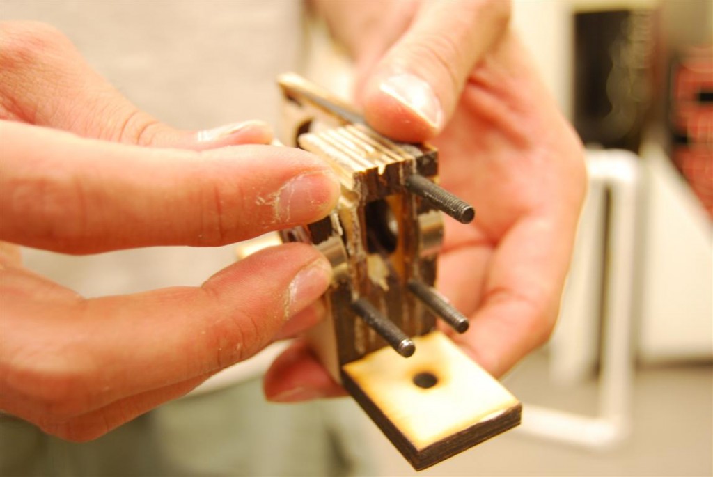
These holes would also need to be made deeper to allow the screws to stick out far enough for springs and nuts to be added on the other side.

Modifications complete

Modifications complete

Bolts sticking out the appropriate distance

Bolts sticking out the appropriate distance

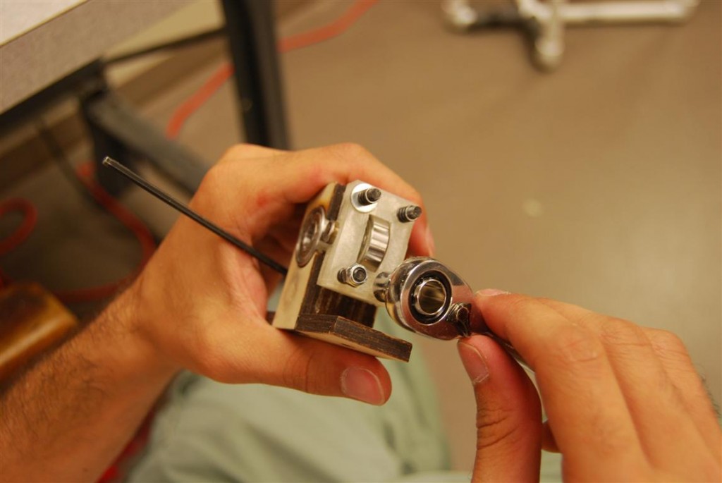
After much modification, we were finally able to get the assembly put together.  Between the two top pictures you can see that the screw holes for mounting the extruder to the reprap are covered by the motor and spring assembly making it impossible to swap the extruder without a complete disassembly of the device.

Assembly of the feeder

Assembly of the feeder

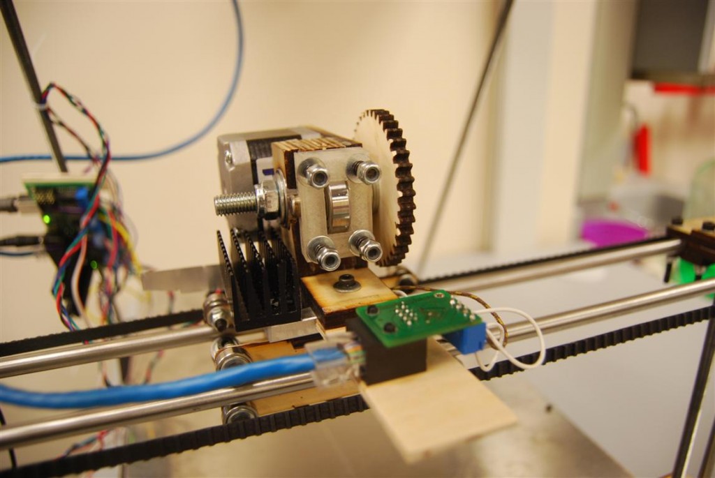
The motor, gears, and extruder drive shaft were then assembled.  One thing we learned later during tuning is that washers need to be added to the extruder drive shaft such that the gripping surface is aligned with the filament.

Extruder finished and mounted

Extruder finished and mounted

The tuning process was mostly concerned with the tension of the four springs.  The problem was that the springs can only be adjusted with the motor removed.  This necessitated the removal of the drive shaft as well because the large gear blocks access to the motor’s mounting screws.

RepRap Mondo – Part 3 – Frame

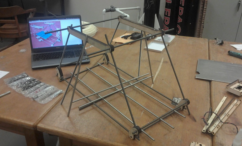
Without instructions, our first task was to identify which rods went where.  Once fitted together it becomes clear where the rods go.

Frame roughly assembled

Frame roughly assembled

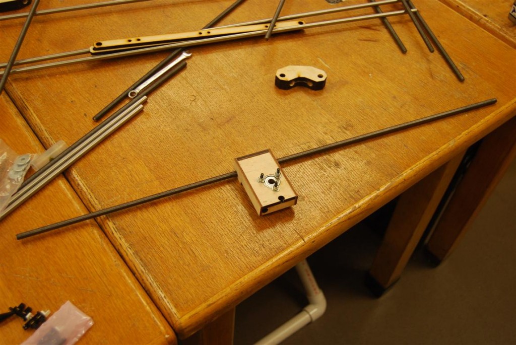
The base mounts for the elevator assembly was then slid on to the long base rod.  Wooden feet were then added as well as washers, and nuts to keep them all in place.

Elevator base slid on to base threaded rod

Elevator base slid on to base threaded rod

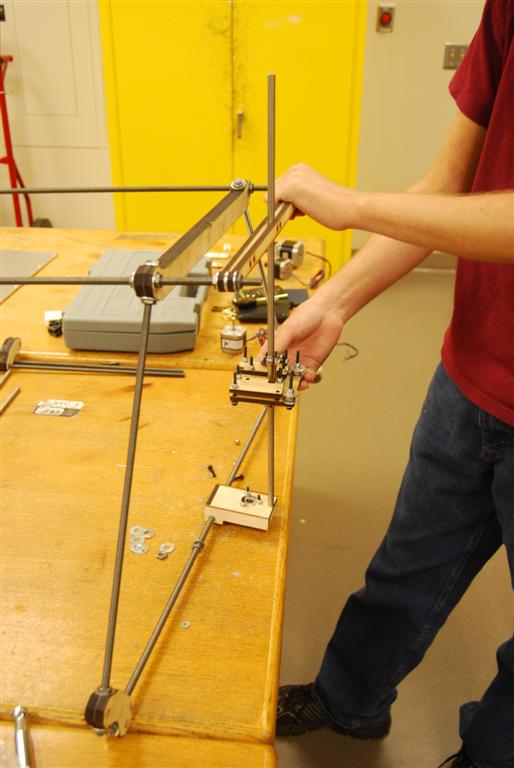
After loosely adding washers and nuts to keep the frame from falling apart, the smooth rod for the elevator assembly was slipped between the two outer pieces of wood.  The base of the rod was then set into the base and the nuts at the top of the structure were adjusted to keep the rod straight vertical.

Elevator assembly rod connected to top of frame

Elevator assembly rod connected to top of frame

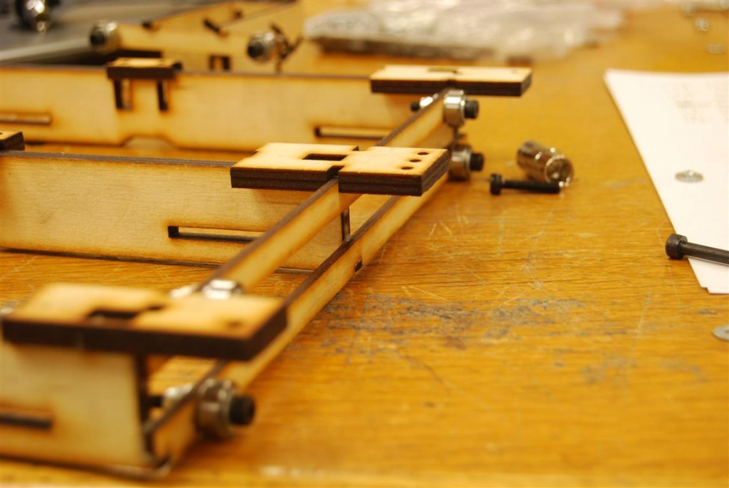
The bed was then prepared by adding roller assemblies to it.  These are similar to those used on the elevator assembly.  On the side shown there are three pairs of two rollers.  On the opposite side there are three pairs of three rollers.  In the middle is a single roller which will sit on top of the center smooth rod.

DSC_0332 (Medium)

Assembling rollers onto bed support

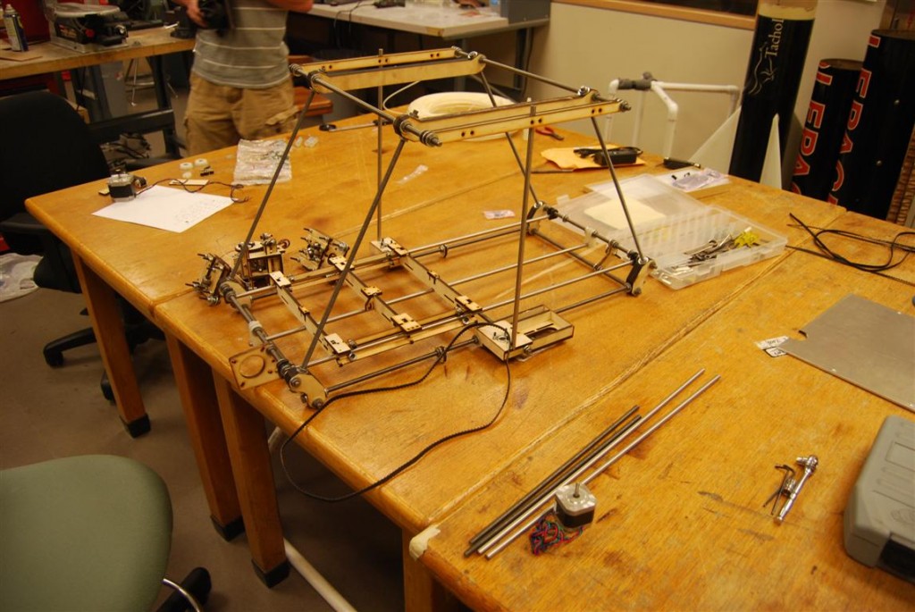
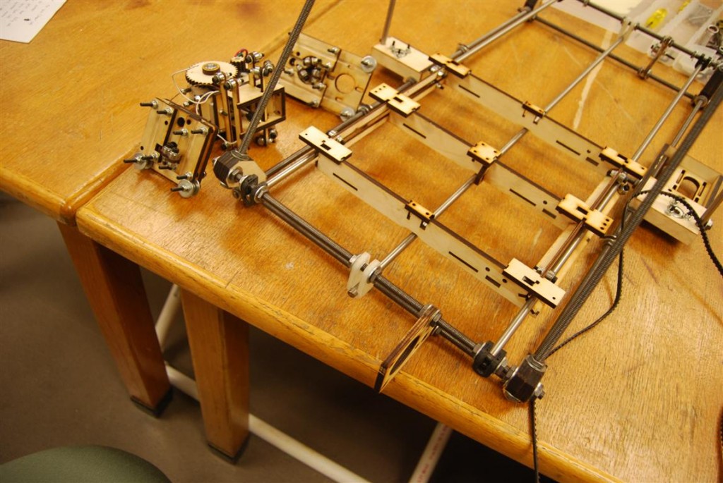
The rods for the bottom of the frame were then slipped together.  The goal being to produce the overall assembly shown below.

High level view

High level view

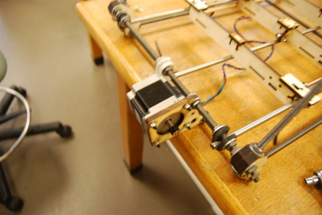
On the motor’s end of the frame, two black rod supports were added on either end.  A longer white support was put in the middle and the motor mount to its right.

Close up of Y-axis motor

Close up of Y-axis motor

On the other side is a similar assembly, but with a roller bracket support in place of the motor.

Bed support

Bed support

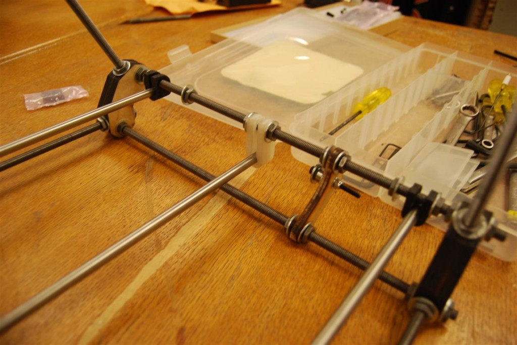
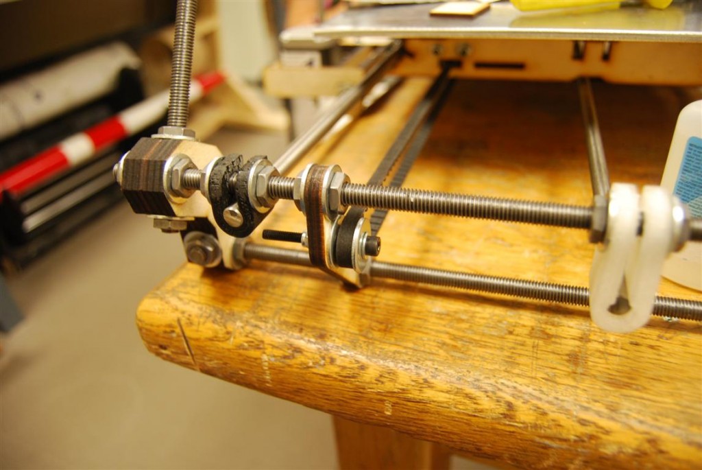
Closer up you can see the multitude of nuts and washers needed to keep everything in its place.  You can also see how the belt will be positioned later on.

Bed support bracket close-up

Bed support bracket close-up

Once everything was loose fitted, the rod with three rollers on it was slid out and the bed installed.  Once the outer frame was squared and leveled, the rod with three rollers was aligned a specific distance from the outer bracket.  The other rod supports were then shifted as needed so that they ran straight under their respective rollers.

Bed positioned for alignment

Bed positioned for alignment

Laser Cutting Airfoils – Results

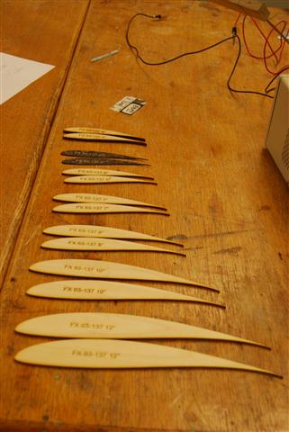
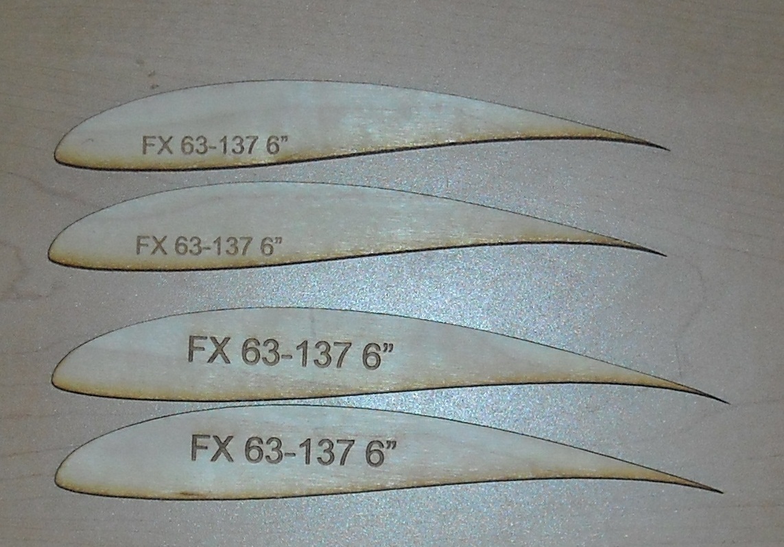
Using the previously detailed calibration method, a number of airfoil profiles were cut.

FX 63-137 Library

FX 63-137 Library

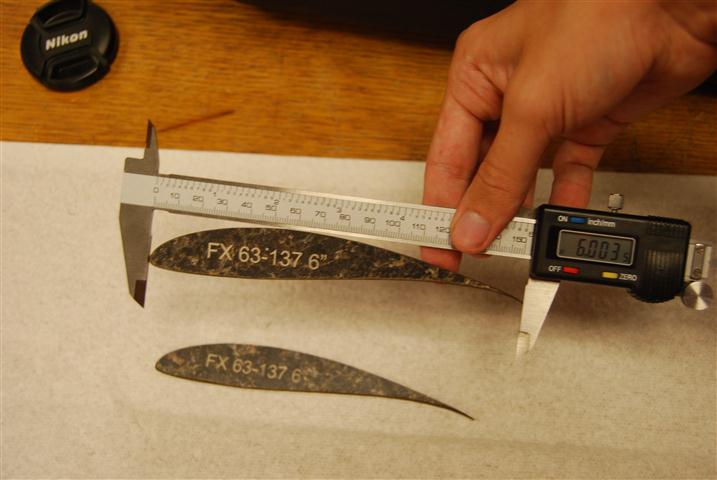
In cutting the airfoils, it was the thin trailing edge that was the greatest source of error due to the thickness of the laser’s cut.  As such, the chord length was used in assessing the accuracy of the airfoil profiles.  To determine the portability of the calibration technique, a 6″ chord airfoil was cut out of 1/8″ Birch Plywood, 1/4 Pine Plywood, and counter top material.  All three materials produced airfoils with an accuracy <0.005″.

FX 63-137 cut out of counter top material

FX 63-137 cut out of counter top material

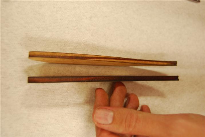
Before using the airfoils, there was some minor sanding required to clean the edges and holes for the pins that needed to be drilled out.  Using high grit sand paper for about a minute produced profiles that were ready for hot wire cutting.

sanding (Small)

1/4" Pine plywood before and after sanding

The 1/8″ birch 6″ FX 63-137 airfoil was used to make a test cut out of 60 PSI foam.  The cut was made difficult due to the lack of a positioning jig piece to go under it.  Despite this, the cut went smoothly and produced the below foam core.

cutFoam (Small)

Quick hot wire cut piece

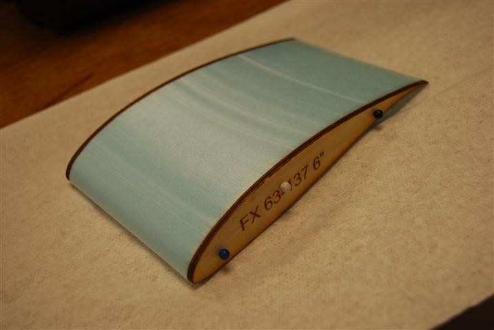
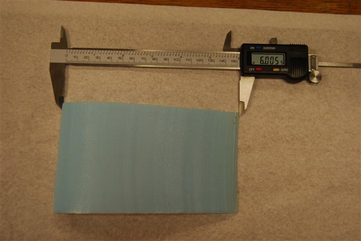
The final foam core was then removed from the profiles.  The surface finish was smoother than it looked.  The trailing edge has a slight bow to it since there were no support jigs to support the wire as it came off the profiles.  Despite this, when measuring the chord length of the core at the edges it was measured at 6.005″.

Final foam core

Final foam core

Laser Cutting Airfoils – Calibration

Power Setting Calibration

Having generated airfoil templates previously, the next step towards creating hot-wire templates was to get them cut.  Thanks to a generous sponsorship, this was accomplished by using Techshop RDU’s  Epilog Helix 24.   For these test pieces 3/8″ Birch Plywood was used.

airfoils

Test Airfoils

After a few test cuts the settings that would allow the piece to be cut after a single pass. were determined to be:

Vector: Speed 15%, Power 90%, Frequency 2000 hz

Additionally, each sample piece was labeled with the source file and dimensions by including a rasterized text.  The settings used were:

Raster:  Speed 25 % Power 80%

While the airfoils were an interesting piece to cut, the reader may clearly observe that in the above image the two six inch chord length airfoils are not the same size.  In fact, neither airfoil came out at six inches.  The smaller airfoil measured 5.8″ and the larger one measured 6.2″.

The cause of this is that while the laser’s cut is very fine, it does still have a thickness.  On the thin trailing edge of the airfoil this thickness results in a large effective change to the geometry.  To compensate for this, the cut line needs to be offset from the desired outline by a certain amount.  Determining this amount is the purpose of the calibration procedure below.

Offset Calibration

Once the settings that will be used for cutting the airfoil have been determined, the offset required may be calculated.  To do this start by cutting a rectangle.  The dimensions are arbitrary, so the actual size doesn’t matter.  During these tests, the setting used to cut the rectangle were etched into the side so they wouldn’t be lost.  After cutting, measure the width of the rectangle and the width of the rectangle’s cutout from the source material.  Subtracting these two measurements and then dividing by two then gives you the the offset to be used for that material.

The calibration can be applied to the laser template in Corel Draw during the below setup procedure.

  1. Open airfoil *.svg
  2. Move airfoil to desired (x,y) position, usually upper left corner
  3. Right-click and unlock airfoil pattern
  4. Click on line and then select all (ctrl-a)
  5. Select “Contour” option from menu
  6. Set contour size according to the calibration results
  7. Right-click and select “Break group apart”
  8. Select all the points on the new contour and set the line width to “hairline”, click apply afterwards
  9. Delete original airfoil
  10. Add label text, right-click and select “convert to curves”
  11. Print to Epilog Laser Cutter using correct settings under properties

Laser Cutting Airfoils – Templates

Using a hotwire technique to cut wings can make wing fabrication much faster and easier.  However, to do so requires that your airfoil go from being data points in a file to a physical guide.  Using a laser cutter to cut wood can make this process quicker and more accurate.  The first step, therefore, is to convert the airfoil data into a form that can be used by the laser cutter.

Sample Airfoil

Sample Airfoil

Airfoil data is nominally stored as a set of coordinates in a space delimited CSV file.  The laser cutter uses vector and raster files to control the laser.  Thus, to control the laser the airfoil coordinates simply need to be converted into a poly-line in an SVG image file.  An SVG file is actually just an XML file and, conveniently, there is a python library for creating these files.

The below code loads, formats, and then creates the polyline.

    scale = 96
    xOffset = 0.5
    yOffset = 2

    pts = ""
    line= 0
    # Read airfoil data
    spamReader = csv.reader(open(filename, 'rb'), delimiter=' ', quotechar='|', skipinitialspace="true")
    for row in spamReader:
        #Skip the first line of header information
        if(line!=0):
            #Format and store in a string
            pts+= str((float(row[0])*chord+xOffset)*scale)+","+str((float(row[1])*-chord+yOffset)*scale)+"  "
        line=1            

    oh=ShapeBuilder()
    mySVG=svg("test")
    #Create a polyline using the formatted airfoil data string
    pl=oh.createPolyline(points=pts,strokewidth=0, stroke='blue')
    mySVG.addElement(pl)

The addition of some code to handle arguments for the airfoil’s filename and chord length and saving the data then finishes the code.  The next step will be to test the pattern on a laser cutter later this week.  The “scale” parameter is determined by Corel Draw which imports svg files at 92 pixels per inch.  The current code is included below.  This version requires the svg module at pySVG.

foil2svg

Sample Files:

FX 63-137 Airfoil

FX 63-137 Template

The program can easily be controlled from the command line using a statement formatted as below.  Where the chord length is defined in inches by the “-c” flag and the airfoil file location by the “-f” flag.  The program will save the output in the same directory and with the same filename as the airfoil except with a *.svg extension.

python foil2svg1.py -c 3 -f ./fx63137sm.dat

*** NOTE pySVG recently updated and is no longer compatible with this program.  A revised version will be available shortly (7/21/2011)

Return top