AUVSI USUAS – NCSU Aerial Robotic Club 2012 Resuts

The following details the mission performance of NC State University’s Aerial Robotics Club at the 10th annual AUVSI Student Unmanned Systems competition.

The autopilot successfully executed a fully autonomous take-off before switching over to manual control due to an error in the autopilot’s altitude configuration.  It was later determined to have been operator error caused by improper zeroing of the altitude.  Autonomous control was regained by flying at a higher altitude than originally planned.  The waypoints, search pattern, and emergent target pattern were flown at this fixed altitude.

One special feature added this year was a laser altimeter.  Despite early concerns of a failure, the altimeter performed well through out the mission.

The SRIC message was determined to be:

John Paul Jones, defeated British ship Serapis in the Battle of Flamborough Head on 23 September 1779

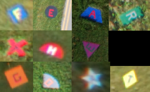
The targets this year spelled out the phrase, “Fear the goat”.  This apparently has something to do with the mascot of the United States Naval Academy “Bill the goat”.

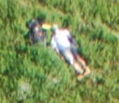
The emergent target this year was a wounded hiker and his backpack.  Most of these details were visible in the images taken with the exception of his wounds.

2012 AUVSI USUAS Results

The 10th annual Undergraduate Student Unmanned Aerial Systems competition hosted by AUVSI’s seafarer chapter concluded last week.  Teams from across the United States, Canada, India, and Turkey converged on Webster naval airfield for several days of autonomous competition.

Final standings

  1. Universite de Sherbrooke
  2. Embry-Riddle (UARE)
  3. California State at Northridge
  4. Delhi Technical University
  5. Cornell University
  6. North Carolina State University
Best Journal – University of Texas at Austin
Best Oral Brief – Kansas State University
Best Mission – Universite de Sherbrooke

 Autopilots

Listed here are some of the autopilots used by various schools.  If you know what autopilots any other schools were using please comment below.

Piccolo

  • North Carolina State University
  • Mississippi University
  • Kansas State University
  • Kansas State University (Pomona)
  • Cornell University
  • New Delhi University

Papparazzi

  • Universite de Sherbrooke
Micropilot
  • Great Mills High School
Custom
  • Utah State (Rotary)

Ardupilot

  • Rutgers University
  • Embry Riddle Prescott

Servo Sin Wave

Automatic code generation is a powerful tool that when combined with Simulink promises important benefits to students and highly complicated applications alike.  Mathworks distributes an Arduino Blockset for Simulink.  The Arduino platform is a desirable to use because of its simple architecture and available hardware.  These hardware options include the ArdupilotMega (APM) which includes sensors and pinouts that will make it easier to integrate into a future aerial vehicle.

While the 2012a version only requires the base Matlab and Simulink packages, NCSU does not currently provide the 2012a version to students.  Instead the 2011a version was used since it was available.  It is not expected that there will be problems using the work done with 2011a in the 2012a release.

The base Arduino blockset includes blocks for Analog and Digital I/O as well as serial communication.  To take full advantage of the capabilites of the APM, additional blocks for SPI, I2C, PPM, and Servos are needed.  Development of a servo blocks has been the focus of this last week.

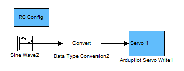
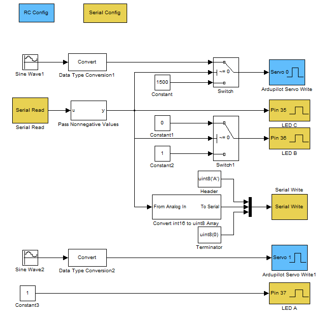
  The new blocks, shown in blue, allow for the configuration and control of servos attached to the APM.  An interesting note  is that although the APM only has 8 servo lines broken out on the side, there are an additional 3 lines (PL3, PB5, and PE3) that can be configured to output PWM commands. These lines are broken out from the APM base-board, but are not available on the sensor-shield “Oilpan”.

With just the blocks from the base, shown in yellow, and the new servo blocks it is already possible to access quite a few of the APM’s functions.  The demonstration program shown above commands two servos through a sin wave motion.  Data is read from the serial port allowing for the functionality of Servo 1 to be switched between sin wave and center position.

Piccolo Telemetry Visualization

The Piccolo Command Center (PCC) software allows an operator to plan and execute flights using the Piccolo autopilot.  However, it can be difficult to analyze post-flight telemetry.  Additionally, access to the PCC software is limited.

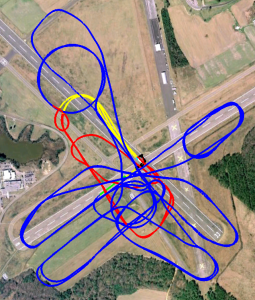
To address this problem I created a matlab function “log2kml.m” to convert Piccolo log files into KML files readable by Google Earth (GE).  This function reads the space delimited log file into Matlab.  It then filters out bad GPS points.  Finally it steps through the data to create a KML polyline.  The line is segmented based on the flight mode to clarify what the autopilot was doing.  The function uses the KML toolbox created by Rafael Fernandes de Oliveira.  It can be found at http://www.mathworks.com/matlabcentral/fileexchange/34694.  This toolbox is put together well and was easy to use.

The results shown below make the high performance of the autopilot clear.  Since the points are 3D there is some distortion of the actual ground path.

AUVSI 2011 NCSU Competition Run

AUVSI 2011 NCSU Competition Run

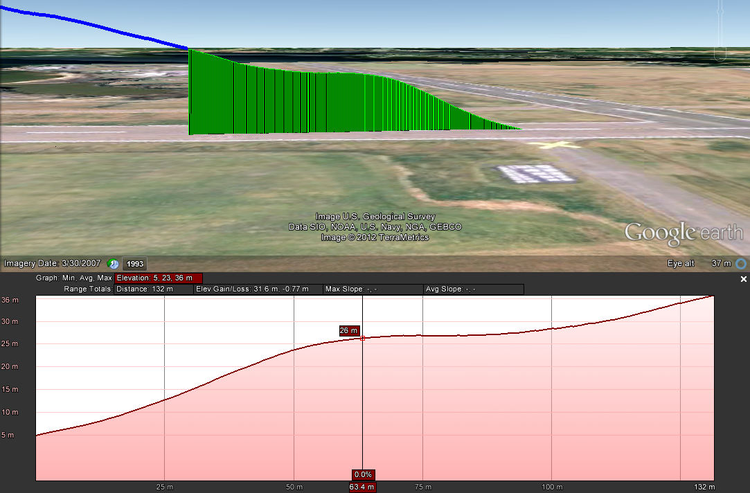
This visualization  allows us to analyze certain maneuvers much more easily.  A point of concern on autonomous take-offs has been a “dip” that occurs as the aircraft switches from prioritizing altitude to prioritizing airspeed.  Using the “Elevation Profile” tool in GE alongside the flight path allows for a clear observation of the performance.

Autonomous Take-off Performance

Autonomous Take-off Performance

It can now clearly be seen that the aircraft does level out, but does not lose altitude.  We can also determine that it levels off at an altitude of 21 meters or 68 feet above ground level.  This new knowledge can now be applied to improving future performance, or at least avoiding flying in to trees at the end of the runway.

For comparison a screenshot from the PCC is shown below.  Since the blue line representing the flight path is so course, the fine motion of the aircraft is only apparent when animated.  The profile view only shows the current position of the aircraft.  Finally, the 3D view isn’t apart of the base software package resulting in the “License Required” text being splashed across the screen.

PCC View

PCC View

AUVSI 2011 SUAS Competition Results

Overall Results

Once the full rankings are released, this list will be updated to include all the teams.  In the meantime, the top five overall teams are listed below.

  1. Utah State University FOSAM
  2. North Carolina State University
  3. Sherbrooke University (Canada)
  4. United States Air Force Academy
  5. Kansas State University
  6. California State University at Northridge

More information and a lot of great photos can be found here at rcgroups.

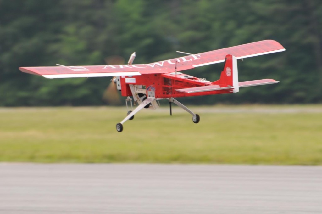
ArcWulf UAV on Autonomous Landing Approach

ArcWulf UAV on Autonomous Landing Approach

Autopilots

The competition offers an excellent opportunity to see what systems other universities are using and to gauge how they performed.

Piccolo

  1. North Carolina State University
  2. United States Air Force Academy
  3. Kansas State University
  4. University of Arizona
  5. Mississippi State University

Paparazzi

  1. Utah State University
  2. Sherbrooke University
  3. M.S. Ramaiah Institute of Technology
  4. Utah States University ROSAM

Ardupilot

  1. Delhi Technical University
  2. Bucknell University
  3. Embry Riddle Aeronautical University
  4. Rutgers University

Micropilot

  1. Florida International University
  2. Great Mills High School

Kestrel

  1. University of California at San Diego

Custom

  1. Hampton Roads Area High School

Simple Necessities

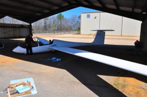
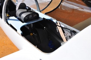
It is sometimes the case that even the most ambitious projects must start off by addressing the most simple of problems.   In this instance a laptop needed to be mounted in the Grobe glider shown below.  The person sitting in front of it also needed to maintain full access to the flight controls and be able to enter and leave the aircraft.

grobe

The Grobe

For this part of the project my role was to be a stand-in pilot as the desk’s support frame was fitted.  The completed frame model is shown below.  It is now being fiberglassed.

DSC_2898 (Medium)

Completed desk frame in the Grobe

This is not an echo

X-CTU

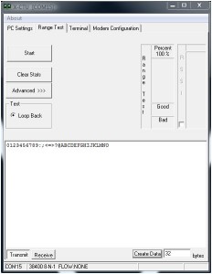
Digi, the manufacturer of zigbees, provides a useful tool for configuring and testing the units.  One feature of this tool is a “Range Test”.  The test is based on the concept of a loop back.  A certain packet is sent from the local zigbee to a remote zigbee.  The remote zigbee then echos the packet back.  By comparing the packet sent to the packet received errors can be detected.  The inclusion of an RSSI measurement makes the tool even more useful.

However, when running the tool with the Ardupilot Mega (v1.02) code running a range test the results returned where abysmal.  An investigation into the code revealed the code shown below.  The critical section is shown in bold where the author choose to copy the default packet into the code and simply transmit it every quarter of a second.  The abysmal results from running the range test were caused by the radios being configured at a different baud rate than the author had assumed.  Additionally, when running the rssi test a delay was introduced which resulted in the tool seeing terrible packet corruption.

test_xbee(uint8_t argc, const Menu::arg *argv)
{
	...
	while(1){
		delay(250);
		// Timeout set high enough for X-CTU RSSI Calc over XBee @ 115200
		Serial3.printf_P(PSTR("0123456789:;<=>?@ABCDEFGHIJKLMNO"));
		//Serial.print("X");
		// Default 32bit data from X-CTU Range Test
		if(Serial.available() > 0){
			return (0);
		}
	}
}

Shown here is a simple implementation of an actual loop back.  This change has been adopted by the Ardupilot project and should be available in the next release.

test_xbee(uint8_t argc, const Menu::arg *argv)
{
	...
	while(1){
                int incomingByte;
                if(Serial3.available()>0){
                      incomingByte = Serial3.read();
                      Serial3.print(incomingByte,byte);
                }
		if(Serial.available() > 0){
			return (0);
		}
	}
}

Telemetry Flight

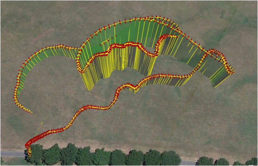
One of the goals with getting the Ardupilot Mega (APM) is to have a means of collecting telemetry information during the flight of an aircraft.  This will have immediate uses during the spring when we start flight testing the senior design aircraft.

flightPath01a

Keeping with this goal I took my aircraft with the APM on-board out for another test flight.  Yesterday’s attempt at telemetry gathering was defeated by a lack of  a defined procedure, so before going out the system was run up on the ground.  With this procedure in mind the same steps were performed at the field.  The result was the telemetry pictured above.  The data confirmed observations of the flight that winds above the tree line were fairly high.  This is shown by the close spacing of the data points on the up wind leg.  The flight was short and the temperatures were freezing, but the data is a significant step in the right direction.

Ardupilot Mega

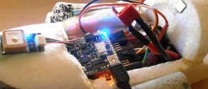
On Thursday the various pieces of my Ardupilot Mega (APM) arrived.  I decided that the APM was worth the expense.  At a minimum the APM will serve as a good practice for working with autonomous systems.  For the past two days I have been reading the manual, assembling, testing, and installing the autopilot on my aircraft.

DSCN0156cropped

In January 2010 I flew a few test flights with the original Ardupilot, however the autopilot was shelved due to a number of issues.  The most prominent issue was that the autopilot was designed with the ability to override the safety switch.  After efforts to find and cut the trace on the board that allowed this function failed the autopilot was not flown again.  Additional efforts to resolve this issue might have been made if the autopilot did not also suffer from poor performance.  The design of the APM fixes this problem allowing the safety pilot to take control at any time.

When purchasing the APM I decided that to avoid compatibility issues and to allow a fair evaluation of the system I would stick to using only components supported by the stock autopilot.  I am using the Mediatek GPS and have added the magnetometer and airspeed sensors to the APM.  I was a bit disappointed when I discovered that the magnetometer is not supported by the latest V1.0 APM software.

After the APM was bench-tested I took it outside for a series of telemetry gathering experiments.  So far I’ve conducted three flights to verify the safety switch and telemetry acquisition functions of the APM.  Unfortunately I have been unable to collect telemetry data in-air.  This may be due in part to my inexperience with the system or some other unknown issue.  To address this I’m working on a set of flight checklists and will be adding radio modems to the system.  This will allow the status of the system to be more easily assessed.

I am looking forward to working with the APM over this winter break and hope to achieve autonomous flight very shortly.  Almost more importantly, I plan to release test data benchmarking the APM against the Piccolo Autopilot.

Making TI and Arduino Talk

Previously simulink was used to program Texas Intrument’s F28335 Delfino processor to simply command a servo through a sine wave.  Since then two more important milestones have been covered; IMU communication and single channel PPM reading.  In both cases the challenge is to correctly configure the existing simulink blocks.

Getting the IMU communication to work was extra challenging because both simulink and the IMU firmware needed to be set-up to communicate.  The IMU is a sparkfun 9-dof board.  This handy board reads three axises of acceleration, gyration, and magnetism.  The board’s MCU contains an atmega328 with the arduino bootloader.  Finally, there is software that can be downloaded to the board to combine the sensor data to get the roll, pitch, and yaw of the board.  By adding the below output option to the output section of the code I can make it send its values in a binary form that the Delfino can read.

if PRINT_BINARY == 1
//Start Character
Serial.print(“S”);
unsigned char lowByte, highByte;
unsigned int val;
//Roll
val = ToDeg(roll)*100;
lowByte = (unsigned char)val;
highByte = (unsigned char)(val >> 8);
Serial.print(lowByte, BYTE);
Serial.print(highByte, BYTE);
//Pitch
val = ToDeg(pitch)*100;
lowByte = (unsigned char)val;
highByte = (unsigned char)(val >> 8);
Serial.print(lowByte, BYTE);
Serial.print(highByte, BYTE);
//Yaw
val = ToDeg(yaw)*100;
lowByte = (unsigned char)val;
highByte = (unsigned char)(val >> 8);
Serial.print(lowByte,BYTE);
Serial.print(highByte,BYTE);
//Ending Character
Serial.print(“E”);

For this to work the code must be set to only output this binary message and do so at 57600 baud.  At higher speeds this board cannot keep up and will send erroneous data which will mess up simulink’s parsing.

On the simulink side, the “Target Preferences block” (In this case F28335 eZdsp) needs to be configured as shown below.
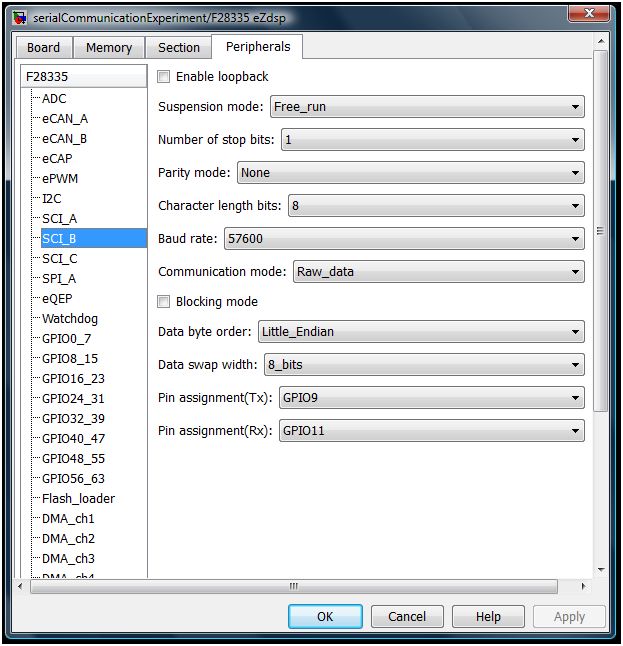
F28335a

The Standard Communication Interface (SCI) module is placed inside of a function which is called by the interrupt handler.  In simulink the top level of the program will look like below.  The demux block after the interrupt block allows the IMU and PWM read to both use the interrupt block and still be called at the correct time.  This is done because each simulink model may only contain a single “Hardware Interrupt” block.headThe Interrupt is then configured to look like the below:
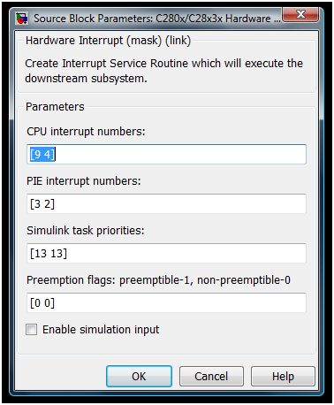
interruptThe first number in each field is related to the SCI interrupt while the second number in each field is for the PPM reader.

The inside of the function includes the SCI module as well as an example use of the data and a GPIO to warn of errors.imuTI

The SCI module should be configured as shown below.
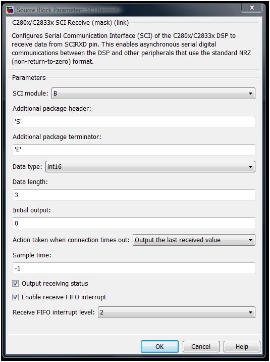
F28335b

Return top