Fuselage Plug Fabrication

Since the beginning of the semester we have made significant strides forward in building our senior design aircraft.  This post will focus on the fabrication of the fuselage plug.  The goal is to produce the fuselage geometry such that it may be used to create molds from which the actual aircraft skins may then be manufactured.

Render of the base plug to be created.

Render of the base plug to be created.

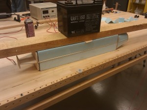
The core of the plug was made using a combination of foam and thin plywood.  As shown below, the plywood bulkhead serve to create the profile shape of the body while the lengthwise pieces of plywood serve to keep the bulkheads positioned and aligned correctly.  Foam blocks where then glued into the spaces and cut using a hot wire bow and a steady hand.  Once cut, the bulkheads are shimmed as needed and the gaps filled with epoxy.

Early stage of plug fabrication

Early stage of plug fabrication

To create the spherical nose of the aircraft, a foam ball from a crafts store was shaved down on a sanding belt until the correct circumference was had.  This was then epoxied to the front bulkhead.  Once all the foam was in place, the remaining seams and imperfections were covered in spackle and sanded down.

Plug covered in spackel ready for sanding

Plug covered in spackel ready for sanding

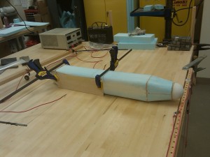
Next, the wing saddle is cut out of the plug.  This wing will sit such that the leading edge and trailing edge will sit flush with the body.  The cut is accomplished by clamping a plywood profile of the bottom of the wing to the plug.  Clamps, screws, and a plywood offset piece all work to keep the profile in place.  Again the cut is completed with a hot wire bow and a steady hand.

wing_saddle_cut

Plug ready for wing saddle to be cut

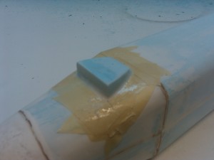
The last remaining feature to be added was the ventilation scope.  The basic shaped was cut out of foam using a template and the hot wire bow.  This was then glue to the plug.  A mix of Capasil and epoxy were then applied along the edge and smoothed with a gloved finger to create a bevel.  After curing, Bondo was used to create a smooth transition from the rear of the scoop to the body.

Initial scoop added to plug

Initial scoop added to plug

With the plug shape complete, the plug was spackeled and sanded several times to get it as smooth as possible.  The plug was then fiberglassed and sanded.  The fiberglass plug was then touched up with Bono before once again being sanded and then spray painted.  A final wet sanding of the painted surface completed the construction of the plug.
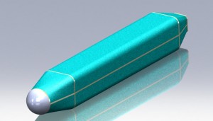
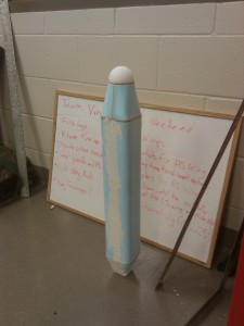
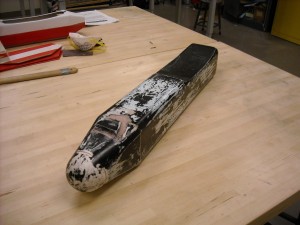
Completed fuselage plug

Completed fuselage plug

Hot Wire Cutting Wings

For our senior design airplane we are building foam core wings.  The technique, which has been popular for years in the senior design program, involves cutting the wing shape out of foam which is subsequently encased in a composite shell.  To cut the wing shape we use a method called hot wire cutting.  As the name suggests, a heated wire is pulled along templates which melts the foam thus forming the wing.  During the process of cutting many wing shapes out of foam I have made some adjustments to the process in order to cut higher quality wings.  The process is particularly well suited to surfaces with blunt edges, but has not been tried on surfaces with taper where the technique may encounter challenges.

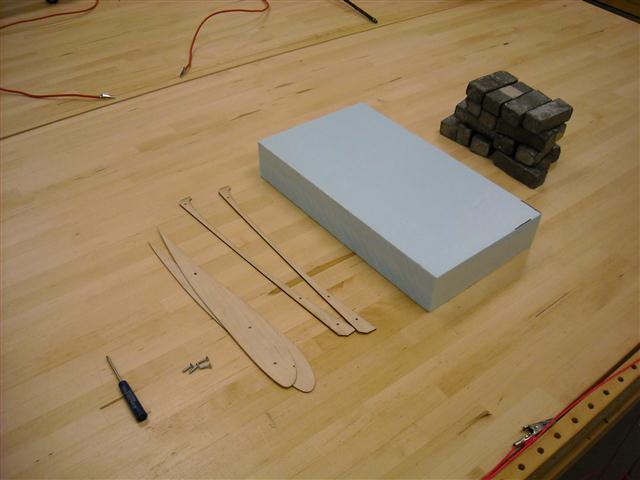
To cut the wings we require a number of tools and supplies:

DSCN0158 (Small)

  1. Foam cut to the planform of the wing (We use highload 60 foam and leave at least a quarter of an inch extra at the leading and trailing edges)
  2. Weights to hold the foam flat and stable
  3. Wing profile shape (We cut ours using a laser cutter, we sure to sand the edges down as smooth as possible)
  4. Bottom Edge profile with offset (Same requirements as the wing profile shape)
  5. Screws and screwdriver
  6. Hot wire bow
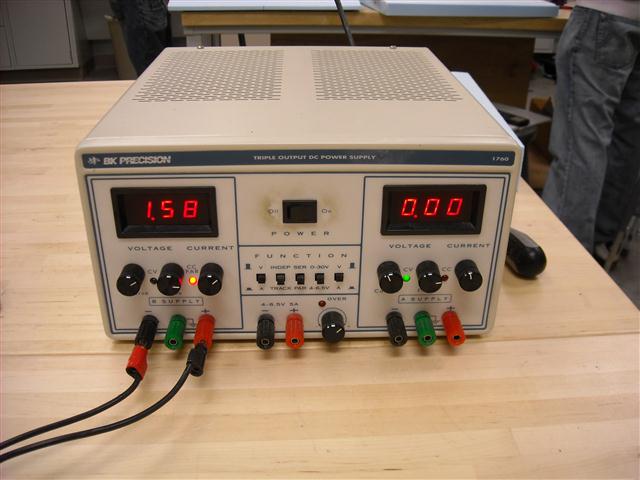
  7. Power Supply (We use a BK Precision 1760 Desktop power supply)

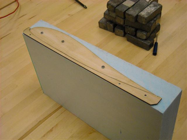
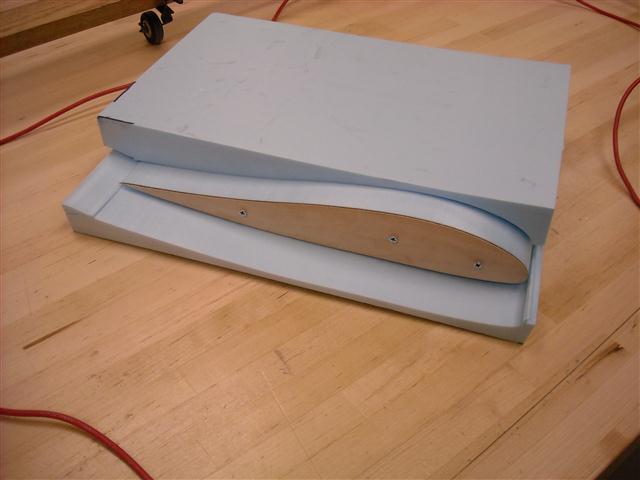
A large clear workspace is desirable for this work.  The first step of the method is to place the profile and offset piece on the end of the wing.  The offset piece serves to position the airfoil a specific distance from the edge of the foam so that it is approximately centered in the foam.  The profile piece is then screwed in.  This is done on both ends of the foam.  We sure to notes which way the profile is facing when creating left panels versus right panels.

DSCN0162 (Small)

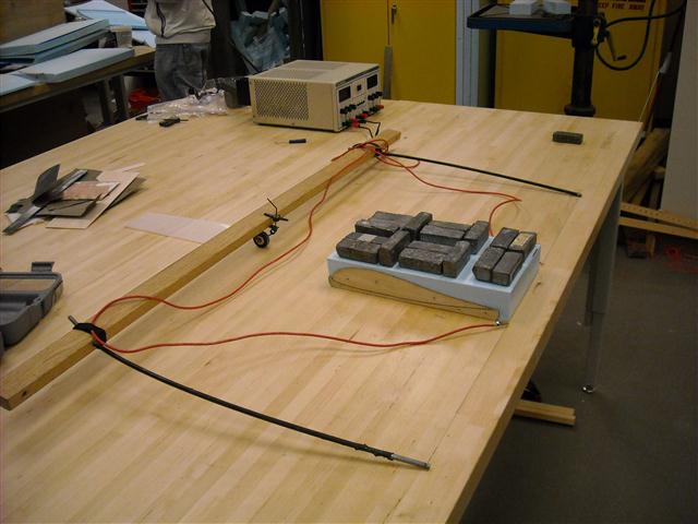
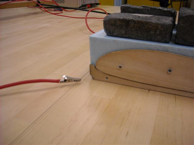
Now place the foam on the table where you will be cutting the piece and place plenty of weight on top.  This serves to prevent the piece from moving as well as keeping it flat on the surface.   The power supply is connected to the bow via clips which are connected close to the edge of the piece to be cut.

DSCN0171 (Small)

The power supply is set to “current mode” by using the leftmost switch located below the on/off switch.  The amount of amps that you will want to set your power supply to will vary based on the type of foam and the type of wire.  For cutting highload 60 and highload 40 insulation foam 1.58 amps +-0.1 amps proved to be the most effective.

DSCN0173 (Small)

The bow is now placed in front of and parallel to the leading edge of the piece.  The power supply is then turned on.  The bow string is pulled along the top edge of the offset piece and then over the top of the profile shape.  The wire outset the power clips will be cool allowing you to work the wire, but be careful to not touch the wire between the clips or the clips themselves.  During this process it is important to keep the bow taut against the profile and pull back at a slow steady pace (<1 cm/sec).  The bow string inside the piece will lag behind the string in your hands.  Try to limit this angle to less than 10 degrees.

Once you reach the end of the piece continue to pull the bow straight out the back.  Now remove the offset piece from the foam.  Placing the bowstring in front of the piece again pull the wire through the foam slightly above the first cut.  When you reach the profile shape pull the wire down and cut the underside of the profile using the same method as the top.

DSCN0177 (Small)

Once the bowstring reaches the end of the profile continue to pull it straight out the back of the foam.  Be sure to turn off the power supply.  You can now remove the weights and pull the foam beds away from the cut piece.

DSCN0178 (Small)

This method produced better results than other methods using the same profile pieces because the foam is always cutting against the wing profile shape.  This specifically prevents the wire from slipping or otherwise unintentionally cutting deeper into the foam than intended as long as the wire is kept at the proper angle across the block.

DSCN0187 (Small)

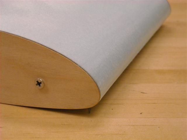
Also, because the wire is being pulled along the same profile for both the upper and lower cuts, what you see is what you get.  This is particularly evident on the trailing edge which came out perfectly straight and uniform during this example piece.

DSCN0183 (Small)

Return top