Cmarc by Aerologic is a tool for computational fluid dynamics. The data generated by this program can be used to determine the flight properties of an aircraft, and with additional work can help determine the stability as well. However, defining the geometry for the aircraft without the Aerlogic Loftsman tool is a difficult task. This is due to the need to mesh various objects together when they intersect. As with many things there are many ways to go wrong during this process and only one way to get it right.
Of particular interest is the connection between the aircraft’s body and the wing. For the purposes of this project the case of wing attached to the top of a cylindrical body was explored. The wing has no dihedral at the intersection and only the bottom of the wing touches the body. The project was built to serve as an extension to Mavl with the code described below all being contained within a new class.
The geometry of the body is defined by two text files. The first file contains the longitudinal profile (X-Z Plane) of the body as shown below.

The second file defines the lateral profile (Y-Z Plane) of the body. The coordinates for this experiment were defined in polar coordinates to simplify the creation of the definition file. Because the section is assumed to be mirrored, only 180 degrees of the profile is defined. The result is the straight line shown below.

This provides all the information needed to then extrude the lateral profile along the longitudinal profile to create the body. The next task was to detect an intersection with the wing and alter the body accordingly. This task must be performed at each slice that intersects. The first section of this code flags the first point that is higher than the bottom of the wing. Assuming the body to be a flat between any two points, the exact point of intersection can be found easily. Knowing this, the angle between the top of the profile and the intersection can be determined. This determines the angle at which the first point must be located. The remaining angle is divided equally amongst the remaining points that need to be drawn (The number of points in the body profiles must remain constant along the entire body). Because the points are equally spaced, any areas of increased resolution in the original profile will be lost. The resulting body points are displayed in matlab as shown below with the points common to the wing shown in blue.

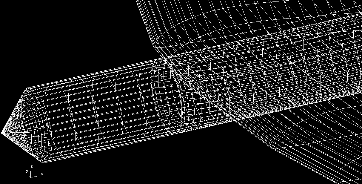
When the process is done correctly, Cmarc will be able to load and process the geometry. The result can be viewed using Aerologic’s Postmarc program. Two such views are shown below.
From the these views it can be seen that the body is being split as it goes under the wing, and then rejoins at the trailing edge.
The next step will be to apply the body’s cutout to the wing. This will create a seamless joint between the two bodies. There are also a two of areas in the code where the assumption of a cylinder was used to get this code to a working state. Removing those assumptions will require a few more hours of work.
The end results is that creating a meshed body is now a process that can be completed in an hour. A significant improvement over the days to weeks it might take otherwise.


