RepRap Mondo – Part 3 – Frame

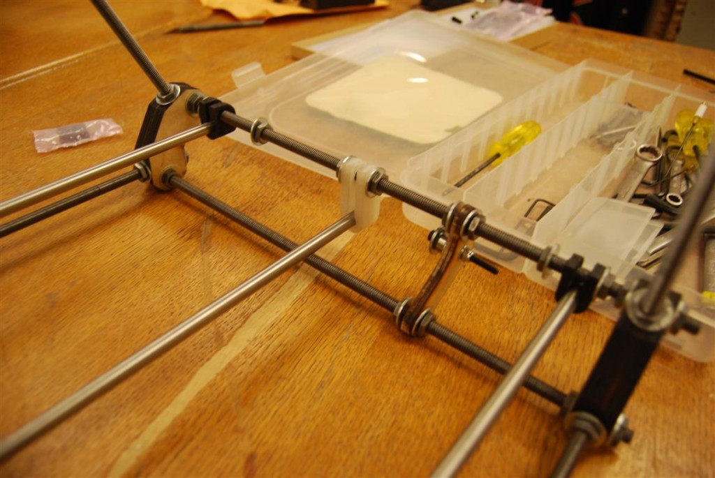
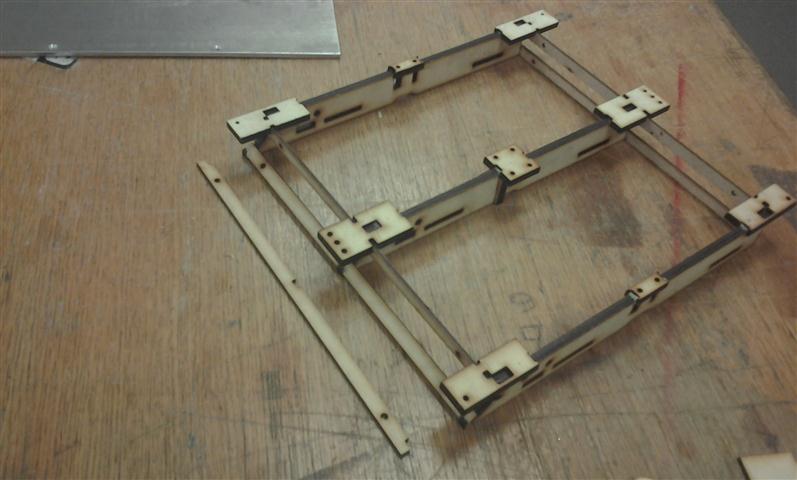
Without instructions, our first task was to identify which rods went where.  Once fitted together it becomes clear where the rods go.

Frame roughly assembled

Frame roughly assembled

The base mounts for the elevator assembly was then slid on to the long base rod.  Wooden feet were then added as well as washers, and nuts to keep them all in place.

Elevator base slid on to base threaded rod

Elevator base slid on to base threaded rod

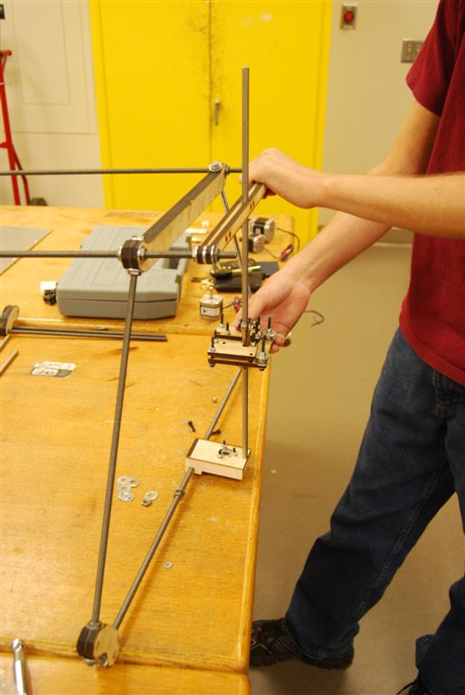
After loosely adding washers and nuts to keep the frame from falling apart, the smooth rod for the elevator assembly was slipped between the two outer pieces of wood.  The base of the rod was then set into the base and the nuts at the top of the structure were adjusted to keep the rod straight vertical.

Elevator assembly rod connected to top of frame

Elevator assembly rod connected to top of frame

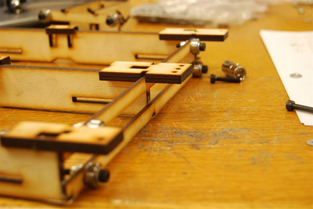
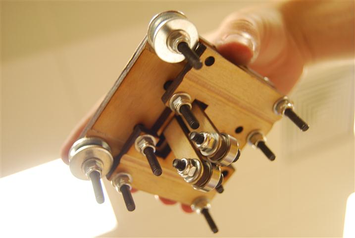
The bed was then prepared by adding roller assemblies to it.  These are similar to those used on the elevator assembly.  On the side shown there are three pairs of two rollers.  On the opposite side there are three pairs of three rollers.  In the middle is a single roller which will sit on top of the center smooth rod.

DSC_0332 (Medium)

Assembling rollers onto bed support

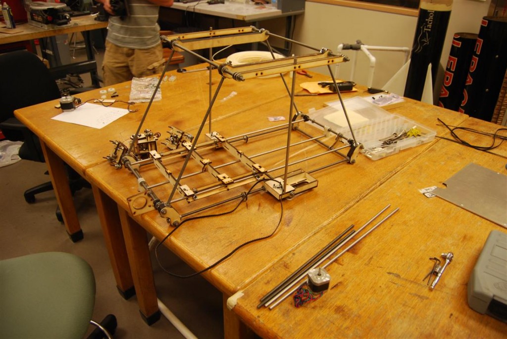
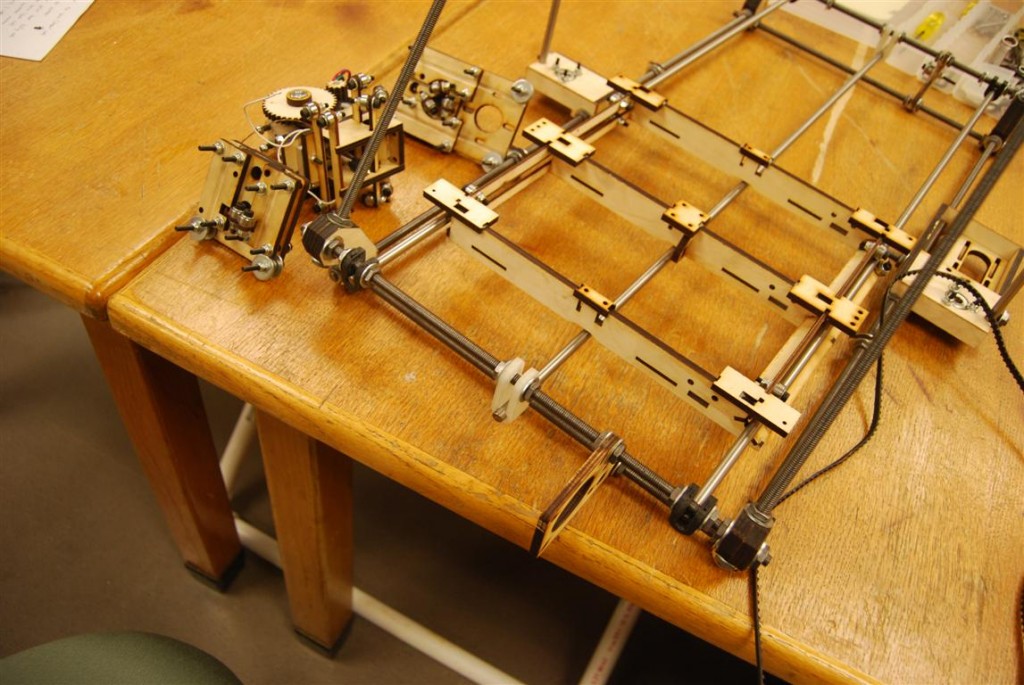
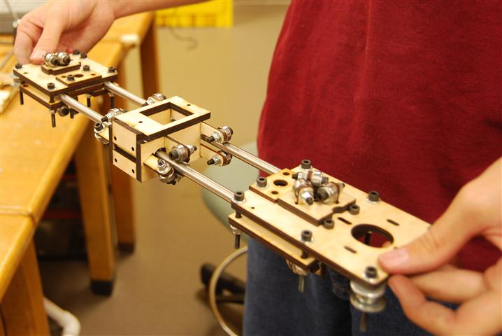
The rods for the bottom of the frame were then slipped together.  The goal being to produce the overall assembly shown below.

High level view

High level view

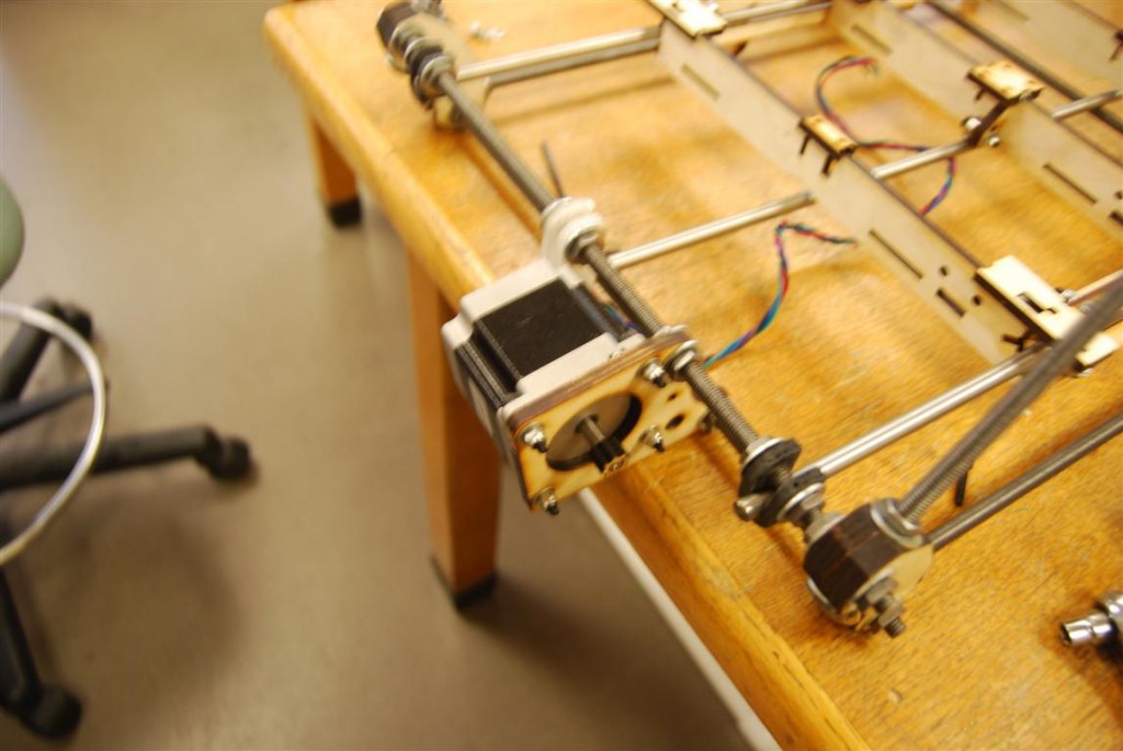
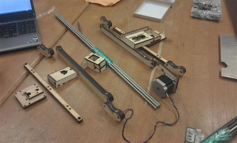
On the motor’s end of the frame, two black rod supports were added on either end.  A longer white support was put in the middle and the motor mount to its right.

Close up of Y-axis motor

Close up of Y-axis motor

On the other side is a similar assembly, but with a roller bracket support in place of the motor.

Bed support

Bed support

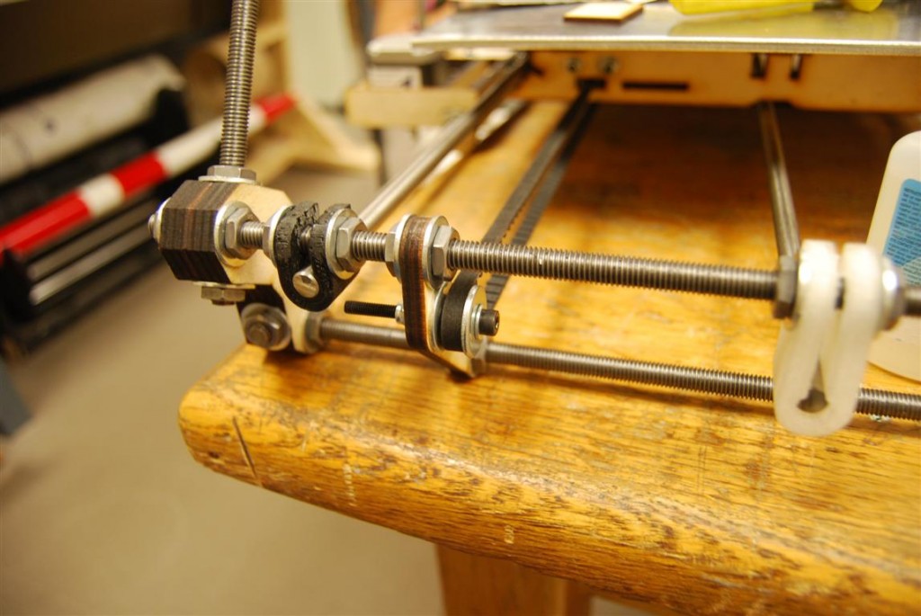
Closer up you can see the multitude of nuts and washers needed to keep everything in its place.  You can also see how the belt will be positioned later on.

Bed support bracket close-up

Bed support bracket close-up

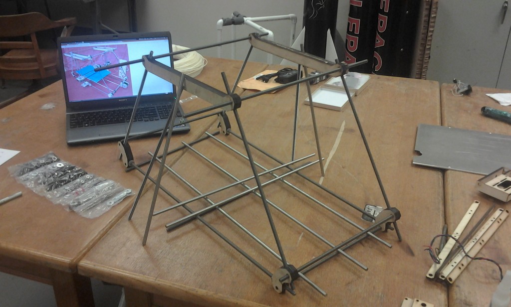
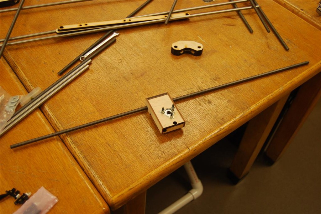
Once everything was loose fitted, the rod with three rollers on it was slid out and the bed installed.  Once the outer frame was squared and leveled, the rod with three rollers was aligned a specific distance from the outer bracket.  The other rod supports were then shifted as needed so that they ran straight under their respective rollers.
Bed positioned for alignment

Bed positioned for alignment

Laser Cutting Airfoils – Results

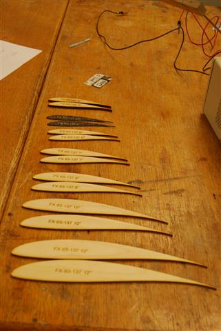
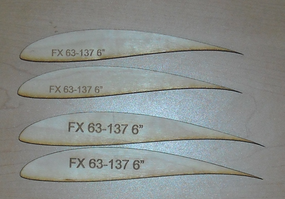
Using the previously detailed calibration method, a number of airfoil profiles were cut.

FX 63-137 Library

FX 63-137 Library

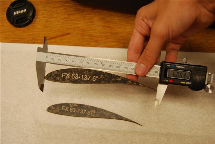
In cutting the airfoils, it was the thin trailing edge that was the greatest source of error due to the thickness of the laser’s cut.  As such, the chord length was used in assessing the accuracy of the airfoil profiles.  To determine the portability of the calibration technique, a 6″ chord airfoil was cut out of 1/8″ Birch Plywood, 1/4 Pine Plywood, and counter top material.  All three materials produced airfoils with an accuracy <0.005″.

FX 63-137 cut out of counter top material

FX 63-137 cut out of counter top material

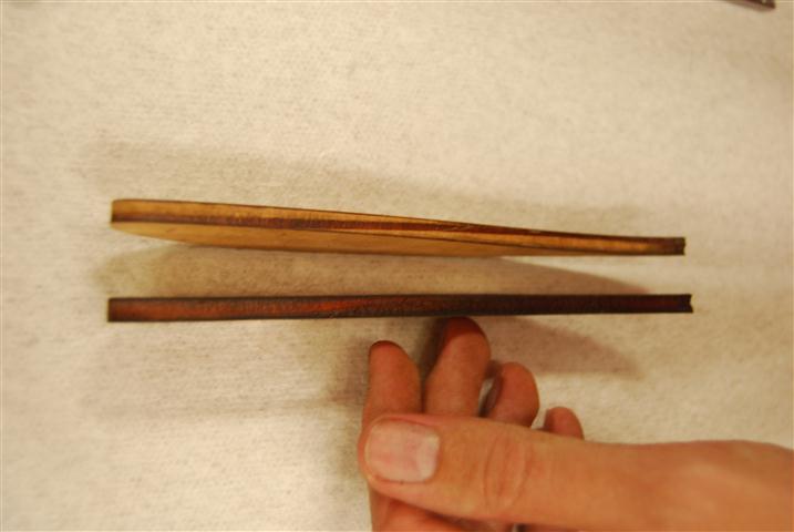
Before using the airfoils, there was some minor sanding required to clean the edges and holes for the pins that needed to be drilled out.  Using high grit sand paper for about a minute produced profiles that were ready for hot wire cutting.

sanding (Small)

1/4" Pine plywood before and after sanding

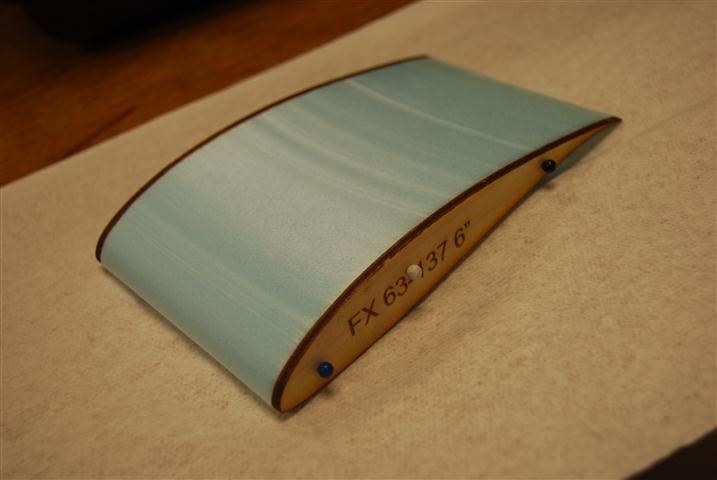
The 1/8″ birch 6″ FX 63-137 airfoil was used to make a test cut out of 60 PSI foam.  The cut was made difficult due to the lack of a positioning jig piece to go under it.  Despite this, the cut went smoothly and produced the below foam core.

cutFoam (Small)

Quick hot wire cut piece

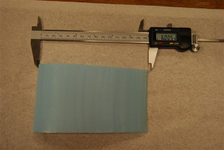
The final foam core was then removed from the profiles.  The surface finish was smoother than it looked.  The trailing edge has a slight bow to it since there were no support jigs to support the wire as it came off the profiles.  Despite this, when measuring the chord length of the core at the edges it was measured at 6.005″.

Final foam core

Final foam core

Laser Cutting Airfoils – Calibration

Power Setting Calibration

Having generated airfoil templates previously, the next step towards creating hot-wire templates was to get them cut.  Thanks to a generous sponsorship, this was accomplished by using Techshop RDU’s  Epilog Helix 24.   For these test pieces 3/8″ Birch Plywood was used.

airfoils

Test Airfoils

After a few test cuts the settings that would allow the piece to be cut after a single pass. were determined to be:

Vector: Speed 15%, Power 90%, Frequency 2000 hz

Additionally, each sample piece was labeled with the source file and dimensions by including a rasterized text.  The settings used were:

Raster:  Speed 25 % Power 80%

While the airfoils were an interesting piece to cut, the reader may clearly observe that in the above image the two six inch chord length airfoils are not the same size.  In fact, neither airfoil came out at six inches.  The smaller airfoil measured 5.8″ and the larger one measured 6.2″.

The cause of this is that while the laser’s cut is very fine, it does still have a thickness.  On the thin trailing edge of the airfoil this thickness results in a large effective change to the geometry.  To compensate for this, the cut line needs to be offset from the desired outline by a certain amount.  Determining this amount is the purpose of the calibration procedure below.

Offset Calibration

Once the settings that will be used for cutting the airfoil have been determined, the offset required may be calculated.  To do this start by cutting a rectangle.  The dimensions are arbitrary, so the actual size doesn’t matter.  During these tests, the setting used to cut the rectangle were etched into the side so they wouldn’t be lost.  After cutting, measure the width of the rectangle and the width of the rectangle’s cutout from the source material.  Subtracting these two measurements and then dividing by two then gives you the the offset to be used for that material.

The calibration can be applied to the laser template in Corel Draw during the below setup procedure.

  1. Open airfoil *.svg
  2. Move airfoil to desired (x,y) position, usually upper left corner
  3. Right-click and unlock airfoil pattern
  4. Click on line and then select all (ctrl-a)
  5. Select “Contour” option from menu
  6. Set contour size according to the calibration results
  7. Right-click and select “Break group apart”
  8. Select all the points on the new contour and set the line width to “hairline”, click apply afterwards
  9. Delete original airfoil
  10. Add label text, right-click and select “convert to curves”
  11. Print to Epilog Laser Cutter using correct settings under properties

Laser Cutting Airfoils – Templates

Using a hotwire technique to cut wings can make wing fabrication much faster and easier.  However, to do so requires that your airfoil go from being data points in a file to a physical guide.  Using a laser cutter to cut wood can make this process quicker and more accurate.  The first step, therefore, is to convert the airfoil data into a form that can be used by the laser cutter.

Sample Airfoil

Sample Airfoil

Airfoil data is nominally stored as a set of coordinates in a space delimited CSV file.  The laser cutter uses vector and raster files to control the laser.  Thus, to control the laser the airfoil coordinates simply need to be converted into a poly-line in an SVG image file.  An SVG file is actually just an XML file and, conveniently, there is a python library for creating these files.

The below code loads, formats, and then creates the polyline.

    scale = 96
    xOffset = 0.5
    yOffset = 2

    pts = ""
    line= 0
    # Read airfoil data
    spamReader = csv.reader(open(filename, 'rb'), delimiter=' ', quotechar='|', skipinitialspace="true")
    for row in spamReader:
        #Skip the first line of header information
        if(line!=0):
            #Format and store in a string
            pts+= str((float(row[0])*chord+xOffset)*scale)+","+str((float(row[1])*-chord+yOffset)*scale)+"  "
        line=1            

    oh=ShapeBuilder()
    mySVG=svg("test")
    #Create a polyline using the formatted airfoil data string
    pl=oh.createPolyline(points=pts,strokewidth=0, stroke='blue')
    mySVG.addElement(pl)

The addition of some code to handle arguments for the airfoil’s filename and chord length and saving the data then finishes the code.  The next step will be to test the pattern on a laser cutter later this week.  The “scale” parameter is determined by Corel Draw which imports svg files at 92 pixels per inch.  The current code is included below.  This version requires the svg module at pySVG.

foil2svg

Sample Files:

FX 63-137 Airfoil

FX 63-137 Template

The program can easily be controlled from the command line using a statement formatted as below.  Where the chord length is defined in inches by the “-c” flag and the airfoil file location by the “-f” flag.  The program will save the output in the same directory and with the same filename as the airfoil except with a *.svg extension.

python foil2svg1.py -c 3 -f ./fx63137sm.dat

*** NOTE pySVG recently updated and is no longer compatible with this program.  A revised version will be available shortly (7/21/2011)

RepRap Mondo – Part 2 – Elevator Assembly

Roller Assembly

Roller Assembly

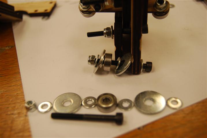
The kit includes (5) short roller mounts and (3) long roller mounts.  As pictured below, a roller assembly is bolted into each of the two holes.  The first roller assembly can be attached with the mount free of the larger assembly.  The second should be attached after being inserted.  Once attached the bolt and lock nut can be screwed down snug.

Roller Assembled

Roller Assembled

Lift Bolt

Lift Bolt

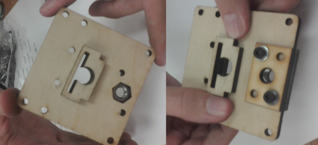
The plate also has a hexagonal cutout for a large nut.  After inserting the nut, the retainer plate can be placed over it.

Elevator Left Assembly

Elevator Left Assembly

Next, the two grooved rectangular plates with the square cutout are added onto the bottom of the long bolt holding the retainer plate on.  Leave these bolts loose for the time being.

DSC_0305 (Small)

Belt Roller Assembly

On each of the outer corners not covered by the last step, a belt roller assembly is added as shown above.

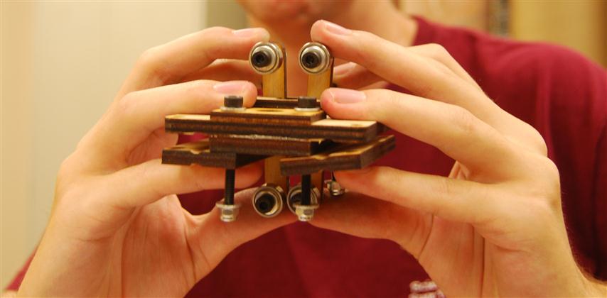
Complete Left Elevator

Complete Left Elevator

The final piece should look similar to the above (One bolt is missing).   The assembly for the right side of the elevator is very similar.  There is just one more set of rollers and the plates with the circular cutout are used instead.

Extruder Mount

Extruder Mount

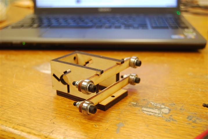
The extruder mount uses the three long roller mounts.  In addition, two roller mounts are already attached to the device and also get rollers.

Elevator Assembly

Elevator Assembly

Finally, the two shorter smooth rods are inserted into the assembly.  Keep the bolts loose enough that the rod length can be adjusted as needed later in the setup.

RepRap Mondo – Part 1 – Unboxing

In May of 2011, http://techzonecom.com LLC introduced the RepRap Mondo.  With a print volume of 18″x12″x11″ it is a big printer.  We decided to purchase the Mondo after getting timely feedback to questions asked of the company.  After a slight delay the printer kit arrived.  What follows will hopefully serve as a guide to others building a Mondo and as a close-up tour of this fascinating machine.

Unboxing

The first surprise was that, as of this time, there are no instructions for how to assemble the Mondo.  The website simply says that its construction is similar to that of the Mendel or Huxley.  However, no one on the team has assembled either of those machines before, and the instructions on the RepRap site were not helpful.  To assemble the Mondo, the pictures of the prototype as posted on the TechZoneCom website were used as our guide.

It is important to note here that because we never had official instructions we cannot be sure that we did everything as it was intended.  All we can claim is that at the end of the project we have a working device.  When official instructions are released, we will edit these posts to note where our version differs.

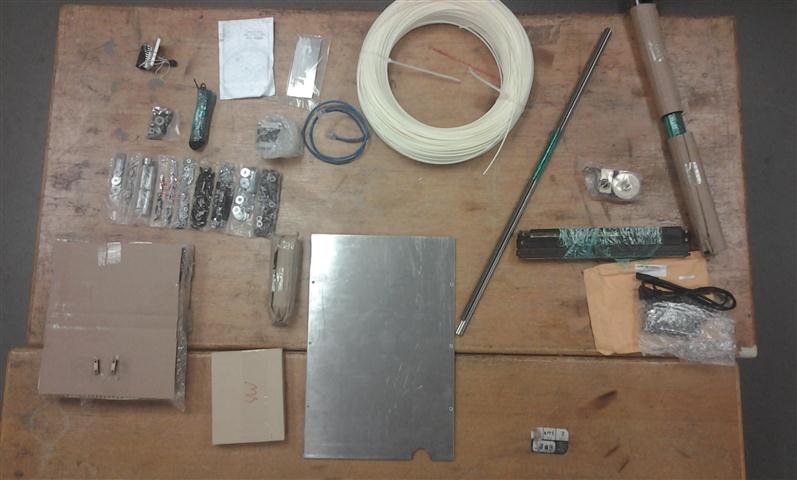
All the parts as taken out of the box

All the parts as taken out of the box

After unboxing the parts, we divided them into a few categories: rods, large frame pieces, small pieces, hardware, and electronics.  Almost everything needed to get the Mondo printing is included except for the printing material and the computer and USB cable to drive it.  We ordered a five pound roll of ABS to go with ours.

Major parts arranged by eventual positions

Major parts arranged by eventual positions

To get a sense of what things were we started by arranging the parts roughly be where they belonged according to the pictures.

Small Parts

Small Parts

The small parts were grouped to keep track of how many we had. Note that the two plates on the bottom left with five holes are stacked two high.  We later discovered that there should have been two of the small piece rectangle with two holes as shown on the top row.  Luckily we were able to fabricate a replacement easily.

Hardware

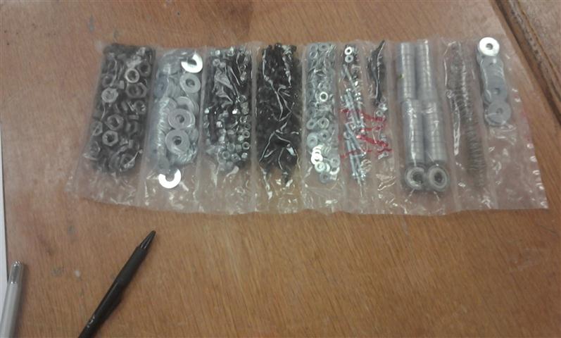
Hardware

Various pieces of hardware used to assemble the device are included in the shown sub-divided plastic bag.  We simply cut one end off to keep the parts organized and accessible.  Some of the parts are mixed together which became frustrating at times.  There are a lot of locking nuts.  Before starting assembly make sure that you have a ratchet set for  the lock nuts.  This will make the assembly go much faster.

Bed support with loose part

Bed support with loose part

A number of the laser cut parts assemblies came pre-glued.  This, without a doubt, saved us many hours of gluing and frustration.  One example is the bed support shown above.  One piece did fall off sometime during transportation, but it was easily re-attached.

AUVSI 2011 SUAS Competition Results

Overall Results

Once the full rankings are released, this list will be updated to include all the teams.  In the meantime, the top five overall teams are listed below.

  1. Utah State University FOSAM
  2. North Carolina State University
  3. Sherbrooke University (Canada)
  4. United States Air Force Academy
  5. Kansas State University
  6. California State University at Northridge

More information and a lot of great photos can be found here at rcgroups.

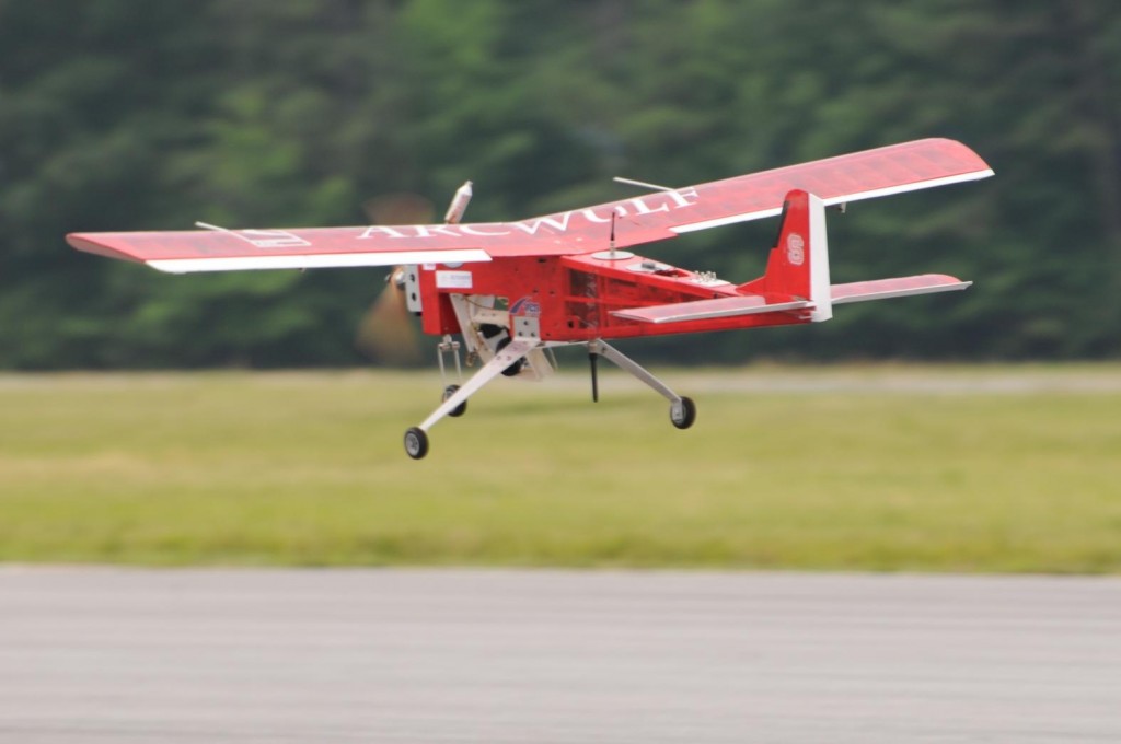
ArcWulf UAV on Autonomous Landing Approach

ArcWulf UAV on Autonomous Landing Approach

Autopilots

The competition offers an excellent opportunity to see what systems other universities are using and to gauge how they performed.

Piccolo

  1. North Carolina State University
  2. United States Air Force Academy
  3. Kansas State University
  4. University of Arizona
  5. Mississippi State University

Paparazzi

  1. Utah State University
  2. Sherbrooke University
  3. M.S. Ramaiah Institute of Technology
  4. Utah States University ROSAM

Ardupilot

  1. Delhi Technical University
  2. Bucknell University
  3. Embry Riddle Aeronautical University
  4. Rutgers University

Micropilot

  1. Florida International University
  2. Great Mills High School

Kestrel

  1. University of California at San Diego

Custom

  1. Hampton Roads Area High School

Entrepreneurship Recognition

The ncsu.edu website was updated today with an article on the engineering entrepreneurship program.  I was pleasantly surprised to see my own face smiling back.

NCSU_Homepage

The funny thing is that I didn’t even win any prizes at the competition.

httpv://www.youtube.com/watch?v=lr2Xo0MJWEY

Vindication Vindicated

After nine months of design and fabrication, on Thursday April 7th my senior design team’s aircraft Vindication flew for the first time.  I had the joy of filming the flight and another team member put the footage together to create the video shown below.

The rapid acceleration of the launch did blow off the hatch, but since it is not flight critical the flight was continued.  Dutch roll can be observed during the flight.  It is particularly evident during low speed flight.  At just under 5 minutes, the flight concluded with a smooth landing.

Raw Footage

NCSU eGames Design and Prototype Challenge

The Entrepreneurship Initiative at NC State runs an annual competition called the eGames.  The games bring students together to compete in different entrepreneurship tasks.  This year I entered the “Design and Prototype Challenge” with a paper detailing the unmanned system that I am currently developing for a client.  Today I received an email that I have qualified to move on to the finalist presentations, so I’ll be presenting at the Entrepreneurship Expo on April 21.

Return top