Simple Necessities

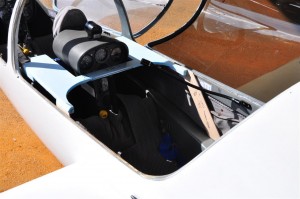
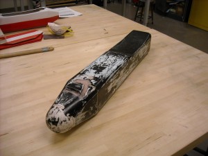
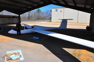
It is sometimes the case that even the most ambitious projects must start off by addressing the most simple of problems.   In this instance a laptop needed to be mounted in the Grobe glider shown below.  The person sitting in front of it also needed to maintain full access to the flight controls and be able to enter and leave the aircraft.

grobe

The Grobe

For this part of the project my role was to be a stand-in pilot as the desk’s support frame was fitted.  The completed frame model is shown below.  It is now being fiberglassed.

DSC_2898 (Medium)

Completed desk frame in the Grobe

Parting Plane Fabrication

Once the fuselage plug has been completed it may now be used as the basis for the fabrication of the fuselage molds.  This process starts with the fabrication of a parting plane.  The parting plane, as its name implies, is used to form the plane between the two halves of the fiberglass mold.  It will only be used for creating the first half of the mold.  The second half will be laid up against the first half.

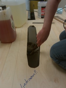
To create the parting plane a rough cut slightly smaller than the body is made with a miter saw into a plywood piece.  This is then carefully sanded down so that the fuselage plug just fits.

parting_plane

Rough parting plane being sanded

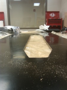
Once the hole is finished, the entire board is sanded, painted, sanded again, and then waxed.  Once this is complete, the parting plane should have an almost mirror-like finish to it.

parting_plane

Mirror finish on completed parting plane

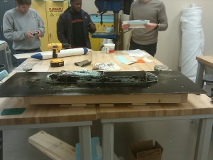
To support the parting plane and hold the plug halfway through the hole, a sub-structure is created under the parting plane.  It is important to ensure that holes drilled will be beyond the area over which fiberglass will be laid for the mold.

parting_plane_substructure

Parting plane with sub-structure and plug

This is not an echo

X-CTU

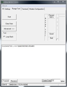
Digi, the manufacturer of zigbees, provides a useful tool for configuring and testing the units.  One feature of this tool is a “Range Test”.  The test is based on the concept of a loop back.  A certain packet is sent from the local zigbee to a remote zigbee.  The remote zigbee then echos the packet back.  By comparing the packet sent to the packet received errors can be detected.  The inclusion of an RSSI measurement makes the tool even more useful.

However, when running the tool with the Ardupilot Mega (v1.02) code running a range test the results returned where abysmal.  An investigation into the code revealed the code shown below.  The critical section is shown in bold where the author choose to copy the default packet into the code and simply transmit it every quarter of a second.  The abysmal results from running the range test were caused by the radios being configured at a different baud rate than the author had assumed.  Additionally, when running the rssi test a delay was introduced which resulted in the tool seeing terrible packet corruption.

test_xbee(uint8_t argc, const Menu::arg *argv)
{
	...
	while(1){
		delay(250);
		// Timeout set high enough for X-CTU RSSI Calc over XBee @ 115200
		Serial3.printf_P(PSTR("0123456789:;<=>?@ABCDEFGHIJKLMNO"));
		//Serial.print("X");
		// Default 32bit data from X-CTU Range Test
		if(Serial.available() > 0){
			return (0);
		}
	}
}

Shown here is a simple implementation of an actual loop back.  This change has been adopted by the Ardupilot project and should be available in the next release.

test_xbee(uint8_t argc, const Menu::arg *argv)
{
	...
	while(1){
                int incomingByte;
                if(Serial3.available()>0){
                      incomingByte = Serial3.read();
                      Serial3.print(incomingByte,byte);
                }
		if(Serial.available() > 0){
			return (0);
		}
	}
}

Fuselage Plug Fabrication

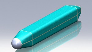
Since the beginning of the semester we have made significant strides forward in building our senior design aircraft.  This post will focus on the fabrication of the fuselage plug.  The goal is to produce the fuselage geometry such that it may be used to create molds from which the actual aircraft skins may then be manufactured.

Render of the base plug to be created.

Render of the base plug to be created.

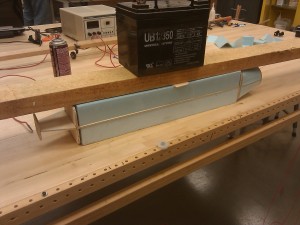
The core of the plug was made using a combination of foam and thin plywood.  As shown below, the plywood bulkhead serve to create the profile shape of the body while the lengthwise pieces of plywood serve to keep the bulkheads positioned and aligned correctly.  Foam blocks where then glued into the spaces and cut using a hot wire bow and a steady hand.  Once cut, the bulkheads are shimmed as needed and the gaps filled with epoxy.

Early stage of plug fabrication

Early stage of plug fabrication

To create the spherical nose of the aircraft, a foam ball from a crafts store was shaved down on a sanding belt until the correct circumference was had.  This was then epoxied to the front bulkhead.  Once all the foam was in place, the remaining seams and imperfections were covered in spackle and sanded down.

Plug covered in spackel ready for sanding

Plug covered in spackel ready for sanding

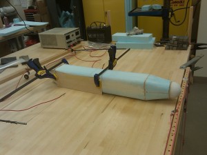
Next, the wing saddle is cut out of the plug.  This wing will sit such that the leading edge and trailing edge will sit flush with the body.  The cut is accomplished by clamping a plywood profile of the bottom of the wing to the plug.  Clamps, screws, and a plywood offset piece all work to keep the profile in place.  Again the cut is completed with a hot wire bow and a steady hand.

wing_saddle_cut

Plug ready for wing saddle to be cut

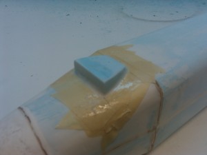
The last remaining feature to be added was the ventilation scope.  The basic shaped was cut out of foam using a template and the hot wire bow.  This was then glue to the plug.  A mix of Capasil and epoxy were then applied along the edge and smoothed with a gloved finger to create a bevel.  After curing, Bondo was used to create a smooth transition from the rear of the scoop to the body.

Initial scoop added to plug

Initial scoop added to plug

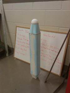
With the plug shape complete, the plug was spackeled and sanded several times to get it as smooth as possible.  The plug was then fiberglassed and sanded.  The fiberglass plug was then touched up with Bono before once again being sanded and then spray painted.  A final wet sanding of the painted surface completed the construction of the plug.

Completed fuselage plug

Completed fuselage plug

Moster Aerospace

I’ve been looking forward to being able to make this post for a long time now.  In the fall of 2010 I was contacted by a business looking for expertise on the Cloud Cap Technologies (CCT) Piccolo autopilot.  To provide this service and others to industry I have started a small business: Moster Aerospace.  I currently provide the following services:

  • Aircraft integration
  • UAS operator (CCT Piccolo)
  • PCC Plugin development (CCT Piccolo)
  • Small aircraft control system development
  • Ardupilot Mega development

If any of these services would be valuable to your business please contact Joseph at 919-449-5085 or at Joe@uavs.us.

logo2First attempt at a logo.

The creation of this logo was the product of boredom and a sudden inspiration.  The logo was created by drawing a sine wave and then overlaying a Taylor series approximation of a saw-wave that used that sine as its starting point.  By continuing this for one and a half cycles, the resulting figure resembles the “M” in Moster.  The remaining lines and circle serve to enclose the figure and make the logo feel more complete.

Hot Wire Cutting Wings

For our senior design airplane we are building foam core wings.  The technique, which has been popular for years in the senior design program, involves cutting the wing shape out of foam which is subsequently encased in a composite shell.  To cut the wing shape we use a method called hot wire cutting.  As the name suggests, a heated wire is pulled along templates which melts the foam thus forming the wing.  During the process of cutting many wing shapes out of foam I have made some adjustments to the process in order to cut higher quality wings.  The process is particularly well suited to surfaces with blunt edges, but has not been tried on surfaces with taper where the technique may encounter challenges.

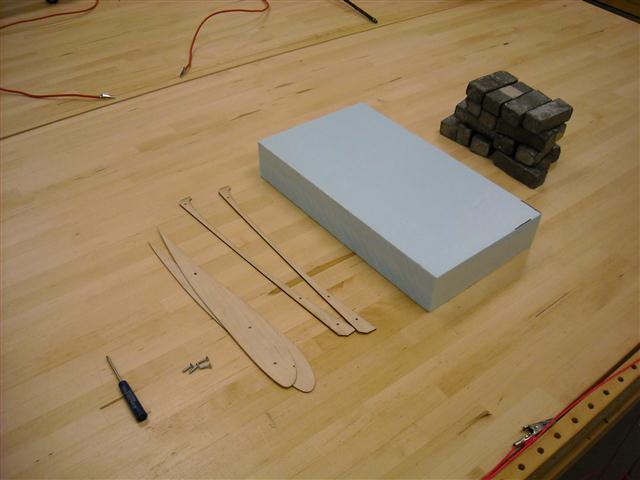
To cut the wings we require a number of tools and supplies:
DSCN0158 (Small)

  1. Foam cut to the planform of the wing (We use highload 60 foam and leave at least a quarter of an inch extra at the leading and trailing edges)
  2. Weights to hold the foam flat and stable
  3. Wing profile shape (We cut ours using a laser cutter, we sure to sand the edges down as smooth as possible)
  4. Bottom Edge profile with offset (Same requirements as the wing profile shape)
  5. Screws and screwdriver
  6. Hot wire bow
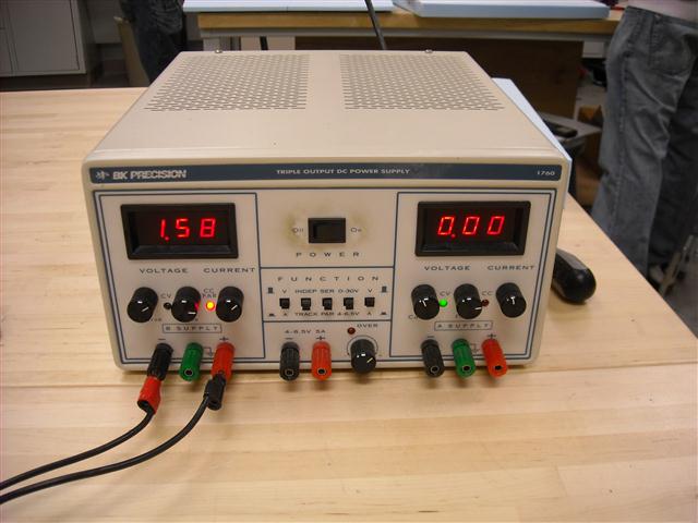
  7. Power Supply (We use a BK Precision 1760 Desktop power supply)

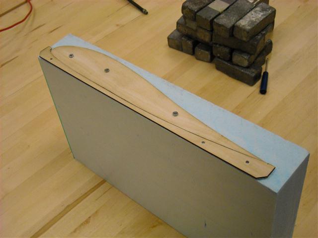
A large clear workspace is desirable for this work.  The first step of the method is to place the profile and offset piece on the end of the wing.  The offset piece serves to position the airfoil a specific distance from the edge of the foam so that it is approximately centered in the foam.  The profile piece is then screwed in.  This is done on both ends of the foam.  We sure to notes which way the profile is facing when creating left panels versus right panels.
DSCN0162 (Small)

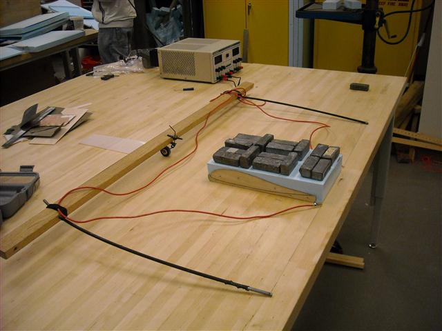
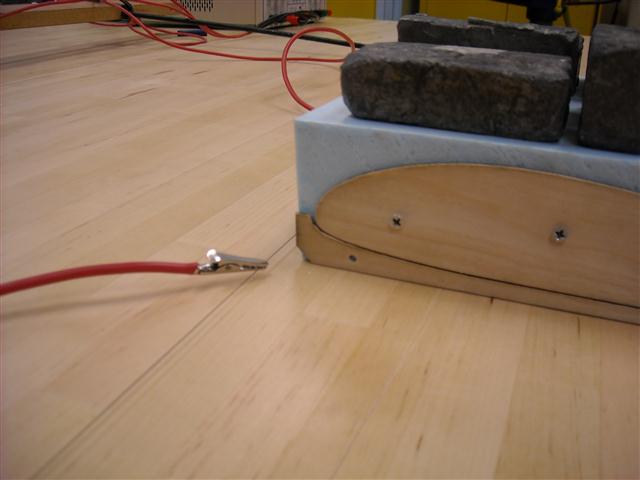
Now place the foam on the table where you will be cutting the piece and place plenty of weight on top.  This serves to prevent the piece from moving as well as keeping it flat on the surface.   The power supply is connected to the bow via clips which are connected close to the edge of the piece to be cut.
DSCN0171 (Small)

The power supply is set to “current mode” by using the leftmost switch located below the on/off switch.  The amount of amps that you will want to set your power supply to will vary based on the type of foam and the type of wire.  For cutting highload 60 and highload 40 insulation foam 1.58 amps +-0.1 amps proved to be the most effective.
DSCN0173 (Small)

The bow is now placed in front of and parallel to the leading edge of the piece.  The power supply is then turned on.  The bow string is pulled along the top edge of the offset piece and then over the top of the profile shape.  The wire outset the power clips will be cool allowing you to work the wire, but be careful to not touch the wire between the clips or the clips themselves.  During this process it is important to keep the bow taut against the profile and pull back at a slow steady pace (<1 cm/sec).  The bow string inside the piece will lag behind the string in your hands.  Try to limit this angle to less than 10 degrees.

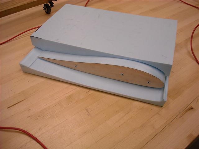
Once you reach the end of the piece continue to pull the bow straight out the back.  Now remove the offset piece from the foam.  Placing the bowstring in front of the piece again pull the wire through the foam slightly above the first cut.  When you reach the profile shape pull the wire down and cut the underside of the profile using the same method as the top.
DSCN0177 (Small)

Once the bowstring reaches the end of the profile continue to pull it straight out the back of the foam.  Be sure to turn off the power supply.  You can now remove the weights and pull the foam beds away from the cut piece.
DSCN0178 (Small)

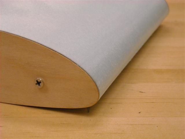
This method produced better results than other methods using the same profile pieces because the foam is always cutting against the wing profile shape.  This specifically prevents the wire from slipping or otherwise unintentionally cutting deeper into the foam than intended as long as the wire is kept at the proper angle across the block.
DSCN0187 (Small)

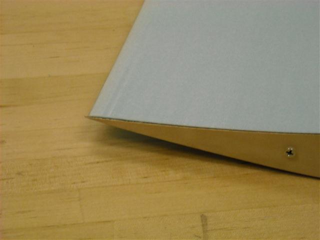
Also, because the wire is being pulled along the same profile for both the upper and lower cuts, what you see is what you get.  This is particularly evident on the trailing edge which came out perfectly straight and uniform during this example piece.
DSCN0183 (Small)

Cmarc Body Modeling

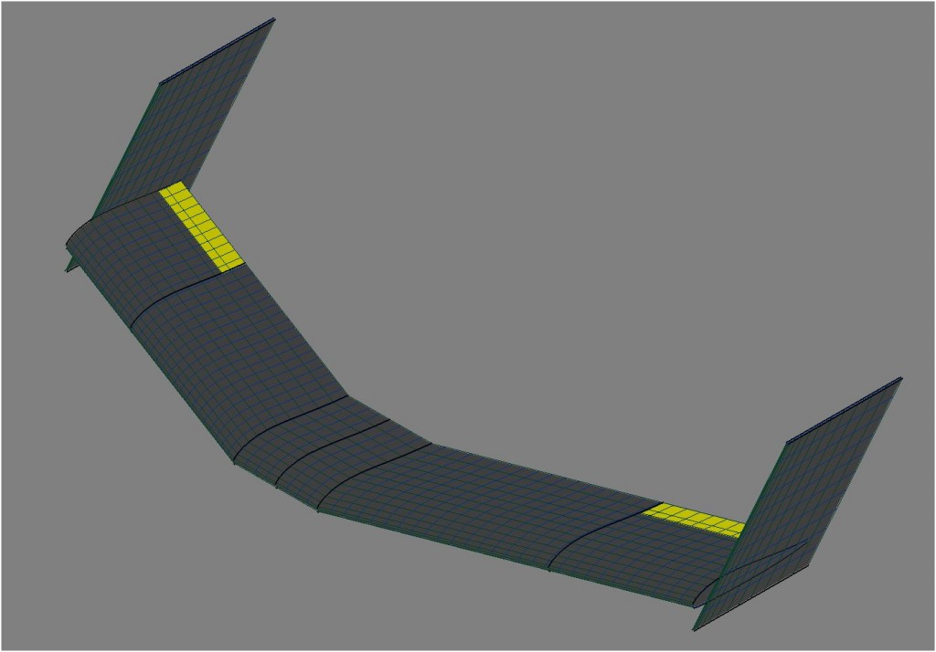
Cmarc by Aerologic is a tool for computational fluid dynamics.  The data generated by this program can be used to determine the flight properties of an aircraft, and with additional work can help determine the stability as well.  However, defining the geometry for the aircraft without the Aerlogic Loftsman tool is a difficult task.  This is due to the need to mesh various objects together when they intersect.  As with many things there are many ways to go wrong during this process and only one way to get it right.

Of particular interest is the connection between the aircraft’s body and the wing.  For the purposes of this project the case of wing attached to the top of a cylindrical body was explored.  The wing has no dihedral at the intersection and only the bottom of the wing touches the body.  The project was built to serve as an extension to Mavl with the code described below all being contained within a new class.

The geometry of the body is defined by two text files.  The first file contains the longitudinal profile (X-Z Plane) of the body as shown below.

profileXZ

The second file defines the lateral profile (Y-Z Plane) of the body.  The coordinates for this experiment were defined in polar coordinates to simplify the creation of the definition file.  Because the section is assumed to be mirrored, only 180 degrees of the profile is defined.  The result is the straight line shown below.

profileTR

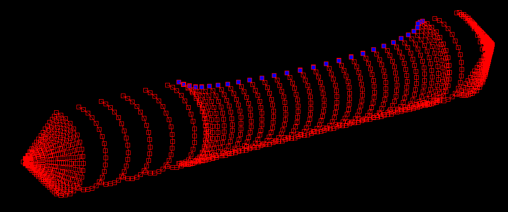
This provides all the information needed to then extrude the lateral profile along the longitudinal profile to create the body.  The next task was to detect an intersection with the wing and alter the body accordingly.  This task must be performed at each slice that intersects.  The first section of this code flags the first point that is higher than the bottom of the wing.  Assuming the body to be a flat between any two points, the exact point of intersection can be found easily.  Knowing this, the angle between the top of the profile and the intersection can be determined.  This determines the angle at which the first point must be located.  The remaining angle is divided equally amongst the remaining points that need to be drawn (The number of points in the body profiles must remain constant along the entire body).  Because the points are equally spaced, any areas of increased resolution in the original profile will be lost.  The resulting body points are displayed in matlab as shown below with the points common to the wing shown in blue.
matlabBody

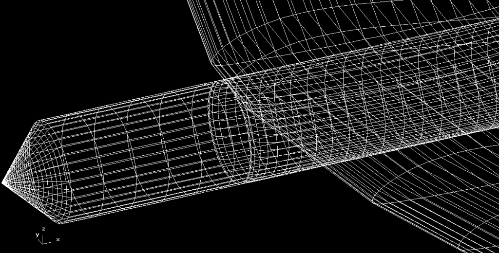
When the process is done correctly, Cmarc will be able to load and process the geometry.  The result can be viewed using Aerologic’s Postmarc program.  Two such views are shown below.
CmarcBody2
From the these views it can be seen that the body is being split as it goes under the wing, and then rejoins at the trailing edge.
CmarcBody
The next step will be to apply the body’s cutout to the wing.  This will create a seamless joint between the two bodies.  There are also a two of areas in the code where the assumption of a cylinder was used to get this code to a working state.  Removing those assumptions will require a few more hours of work.
The end results is that creating a meshed body is now a process that can be completed in an hour.  A significant improvement over the days to weeks it might take otherwise.

Telemetry Flight

One of the goals with getting the Ardupilot Mega (APM) is to have a means of collecting telemetry information during the flight of an aircraft.  This will have immediate uses during the spring when we start flight testing the senior design aircraft.

flightPath01a

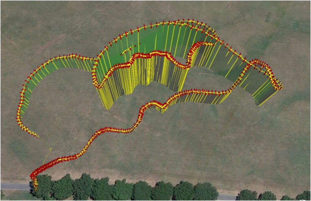
Keeping with this goal I took my aircraft with the APM on-board out for another test flight.  Yesterday’s attempt at telemetry gathering was defeated by a lack of  a defined procedure, so before going out the system was run up on the ground.  With this procedure in mind the same steps were performed at the field.  The result was the telemetry pictured above.  The data confirmed observations of the flight that winds above the tree line were fairly high.  This is shown by the close spacing of the data points on the up wind leg.  The flight was short and the temperatures were freezing, but the data is a significant step in the right direction.

Ardupilot Mega

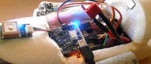
On Thursday the various pieces of my Ardupilot Mega (APM) arrived.  I decided that the APM was worth the expense.  At a minimum the APM will serve as a good practice for working with autonomous systems.  For the past two days I have been reading the manual, assembling, testing, and installing the autopilot on my aircraft.

DSCN0156cropped

In January 2010 I flew a few test flights with the original Ardupilot, however the autopilot was shelved due to a number of issues.  The most prominent issue was that the autopilot was designed with the ability to override the safety switch.  After efforts to find and cut the trace on the board that allowed this function failed the autopilot was not flown again.  Additional efforts to resolve this issue might have been made if the autopilot did not also suffer from poor performance.  The design of the APM fixes this problem allowing the safety pilot to take control at any time.

When purchasing the APM I decided that to avoid compatibility issues and to allow a fair evaluation of the system I would stick to using only components supported by the stock autopilot.  I am using the Mediatek GPS and have added the magnetometer and airspeed sensors to the APM.  I was a bit disappointed when I discovered that the magnetometer is not supported by the latest V1.0 APM software.

After the APM was bench-tested I took it outside for a series of telemetry gathering experiments.  So far I’ve conducted three flights to verify the safety switch and telemetry acquisition functions of the APM.  Unfortunately I have been unable to collect telemetry data in-air.  This may be due in part to my inexperience with the system or some other unknown issue.  To address this I’m working on a set of flight checklists and will be adding radio modems to the system.  This will allow the status of the system to be more easily assessed.

I am looking forward to working with the APM over this winter break and hope to achieve autonomous flight very shortly.  Almost more importantly, I plan to release test data benchmarking the APM against the Piccolo Autopilot.

Introducing Vindication

These last weeks have been quite a challenge with mounting school work and even a brief hospitalization (appendicitis).  Despite this my team and I have made great progress on our UAV.  The aircraft also has a name now “Vindication”.  We named the aircraft as such, because when completed. that it what the aircraft will become for all our hard work.

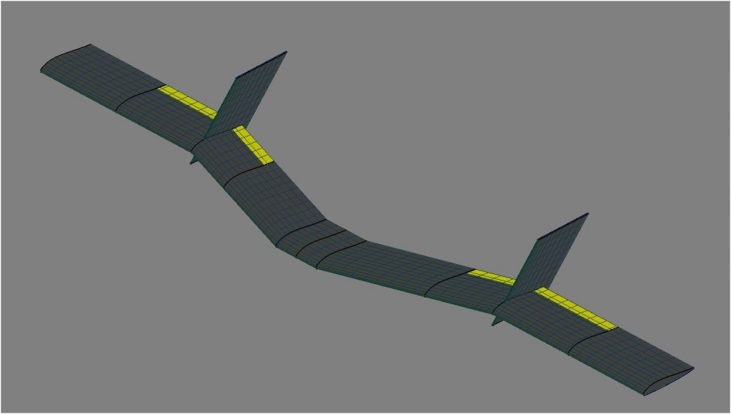
To address the challenge of creating a multi-configuration UAV I came up with the idea of using wing plate extensions.  However, in adding these extensions we did not want to have to readjust the center of gravity in order to maintain a static margin of 10%.  Thus the extensions are designed such that the change in neutral point due to the extensions is equal to the change in the center of gravity due to the added weight of the extensions.  This resulted in what we have been calling the “Lambda Wing” because of it’s transition from a swept wing to the straight wing.

AVL-LS

Low Speed Configuration

There is still a long way to go.  The next step will be to model the aircraft in Cmarc which when properly completed will be considered our truth model.

High Speed Configuration

High Speed Configuration

Both of these aircraft’s models were generated using the Mavl tool.  The tool’s functionality has grown considerably since its last mention hear, but it is interesting to note the the total line count has actually stayed almost constant at 1500 lines for the last eight weeks.  The rate at which code has been compressed has very coincidentally matched the rate at which new code is being added.  The Mavl tool is now fully capable of modelling an arbitrary aircraft (including control surfaces) as well as analyzing the stability and performance of the resultant aircraft.  The analysis tools include stall and cruise speed calculations thanks to the XFoil bridge being added.  It goes without saying that the tool is also capable of classifying the eigenvalues produced by AVL to determine the flight modes of the aircraft.  There is even a tool for correlating the flight modes to the handling levels as defined in MIL-F-8785.

Return top